
Datasheet


Change the pins to the following to match the wiring on the Raspberry Pi:
ecs = digitalio.DigitalInOut(board.CE0)
dc = digitalio.DigitalInOut(board.D22)
srcs = None
rst = digitalio.DigitalInOut(board.D27)
busy = digitalio.DigitalInOut(board.D17)
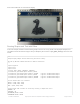
Now go to the command prompt on your Raspberry Pi and run the script with the following command:
python3 epd_bitmap.py
After a few seconds, your display should show this image:
Full Example Code
Here is the full example code.
To run the code sample below, you will need to change the pins the same way as you did in the Tri-color
Bitmap Example.
© Adafruit Industries https://learn.adafruit.com/adafruit-eink-display-breakouts Page 44 of 61