
Datasheet


Arduino Code
Wiring
Wiring up the display in SPI mode is pretty easy as there's not that many pins! We'll be using hardware SPI, but you can
also use software SPI (any pins) later.
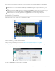
Start by connecting the power pins
3-5V Vin connects to the microcontroller board's 5V or 3.3V power supply pin
GND connects to ground
Required SPI Pins
These use the hardware SPI interface and is required so check your microcontroller board to see which pins are
hardware SPI
CLK connects to SPI clock. On Arduino Uno/Duemilanove/328-based, thats Digital 13. (For other Arduino-
compatibles See SPI Connections for more details (https://adafru.it/d5h))
MISO connects to SPI MISO. On Arduino Uno/Duemilanove/328-based, thats Digital 12. (For other Arduino-
compatibles See SPI Connections for more details (https://adafru.it/d5h))
MOSI connects to SPI MOSI. On Arduino Uno/Duemilanove/328-based, thats Digital 11. (For other Arduino-
compatibles See SPI Connections for more details (https://adafru.it/d5h))
Other Digital I/O Pins
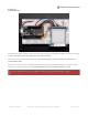
Do not update more than once every 180 seconds or you may permanently damage the display
The pin outs are identical for the 1.54", 2.13" and 2.7" E-Ink display!
© Adafruit Industries https://learn.adafruit.com/adafruit-eink-display-breakouts Page 20 of 61