
Datasheet


Pinouts
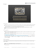
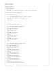
Power Pins
Vin - this is the power pin. Since the sensor chip uses 3 VDC, we have included a voltage regulator on board that
will take 3-5VDC and safely convert it down. To power the board, give it the same power as the logic level of
your microcontroller - e.g. for a 5V microcontroller like Arduino, use 5V
3Vo - this is the 3.3V output from the voltage regulator, you can grab up to 100mA from this if you like
GND - common ground for power and logic
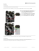
I2C Logic Pins
SCL - I2C clock pin, connect to your microcontroller's I2C clock line. This pin is level shifted so you can use 3-5V
logic, and there's a 10K pullup on this pin.
SDA -I2C data pin, connect to your microcontroller's I2C data line. This pin is level shifted so you can use 3-5V
logic, and there's a 10K pullup on this pin.
STEMMA QT (https://adafru.it/Ft4) - These connectors allow you to connectors to dev boards with STEMMA QT
connectors or to other things with various associated accessories (https://adafru.it/Ft6)
Bottom Row SDO - The default I2C address is 0x6A When using I2C, this pin can be tied to 3.3V to set the I2C
address to 0x6B
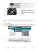
SPI Logic pins:
All pins going into the breakout have level shifting circuitry to make them 3-5V logic level safe. Use whatever logic
level is on Vin!
SCK - This is
also
the SPI Clock pin, it's an input to the chip
DO - this is the Serial Data Out / Master In Slave Out pin, for data sent from the LSM6DSOX or ISM330DHCX to
your processor.
© Adafruit Industries https://learn.adafruit.com/lsm6dsox-and-ism330dhc-6-dof-imu Page 6 of 23