
User Manual
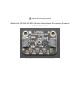


your microcontroller - e.g. for a 5V micro like Arduino, use 5V, for a feather use 3.3V
3Vo - this is the 3.3V output from the voltage regulator, you can grab up to 100mA from this if you like
GND - common ground for power and logic
I2C Logic pins:
SCK - this is the I2C clock pin, connect to your microcontrollers I2C clock line.
SDI - this is the I2C data pin, connect to your microcontrollers I2C data line.
Leave the SDO and CS pins disconnected
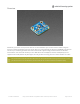
SPI Logic pins:
All pins going into the breakout have level shifting circuitry to make them 3-5V logic level safe. Use whatever logic
level is on Vin!
SCK - This is
also
the SPI Clock pin, its an input to the chip
SDO - this is the Serial Data Out / Master In Slave Out pin, for data sent from the LPS35HW to your processor
SDI - this is
also
the Serial Data In / Master Out Slave In pin, for data sent from your processor to the LPS35HW
CS - this is the Chip Select pin, drop it low to start an SPI transaction. Its an input to the chip
If you want to connect multiple LPS35HW's to one microcontroller, have them share the SDI, SDO and SCK pins. Then
assign each one a unique CS pin.
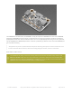
Other pins
INT is the interrupt output pin. You can configure the interrupt to trigger for various 'reasons' such as going over
or under a configured pressure threshold. Voltage level is the same as Vcc.
The low pressure threshold interrupt only works when the LPS33W/LPS35HW are operating in relative mode.
© Adafruit Industries https://learn.adafruit.com/lps35hw-water-resistant-pressure-sensor Page 9 of 28