
User Manual

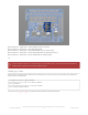
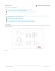


Table Of Contents
- Guide Contents
- Overview
- Assembly
- Solder on Headers and Terminal Block
- Powering Motors
- Voltage requirements:
- Current requirements:
- Power it up
- Installing Software
- Enable I2C
- Python Installation of MotorKit Library
- Using DC Motors
- Connecting DC Motors
- Controlling DC Motors
- Full Example Code
- Using Stepper Motors
- Connecting Stepper Motors
- Controlling Stepper Motors
- Stepping
- Full Example Code
- Python Docs
- Stacking HATs
- Addressing the HATs
- Stacking in Code
- Downloads
- Files
- Schematic
- Fabrication Print
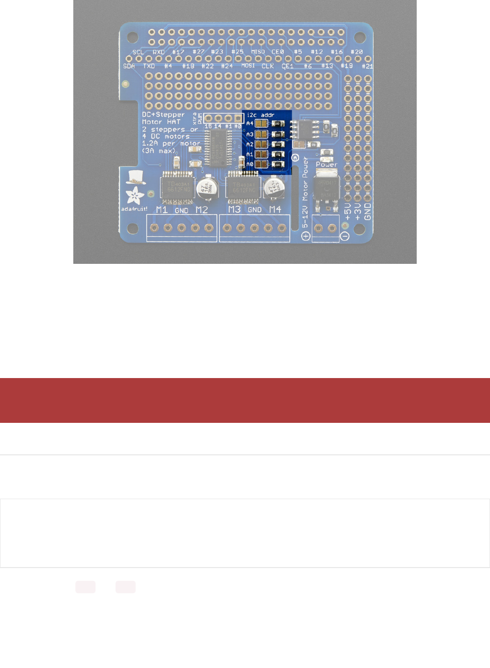
Board 0: Address = 0x60 Offset = binary 0000 (no jumpers required)
Board 1: Address = 0x61 Offset = binary 0001 (bridge A0)
Board 2: Address = 0x62 Offset = binary 0010 (bridge A1, the one above A0)
Board 3: Address = 0x63 Offset = binary 0011 (bridge A0 & A1, two bottom jumpers)
Board 4: Address = 0x64 Offset = binary 0100 (bridge A2, middle jumper)
etc.
Stacking in Code
Now that you've changed the I2C address on the hardware, you need to set it in your code. When you initialise the
class, you can set the address.
Then you can use kit1 and kit2 to control the motors attached to the associated hat.
Note that address 0x70 is the "all call" address for the controller chip on the HAT. All boards will respond to
address 0x70 - regardless of the address jumper settings.
from adafruit_motorkit import MotorKit
# Initialise the first hat on the default address
kit1 = MotorKit()
# Initialise the second hat on a different address
kit2 = MotorKit(address=0x61)
© Adafruit Industries
https://learn.adafruit.com/adafruit-dc-and-stepper-motor-hat-for-raspberry-
pi
Page 26 of 31