
User Manual

I
2
CDriver User Guide 17
i display status information (uptime, voltage, current, temperature)
d device scan
w dev bytes write bytes to I
2
C device dev
p send a STOP
r dev N read N bytes from I
2
C device dev, then STOP
m enter I
2
C bus monitor mode
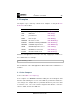
For example the command:
i2ccl /dev/ttyUSB0 r 0x48 2
reads two bytes from the I
2
C device at address 0x48. So with an LM75B tem-
perature sensor connected you might see output like:
0x16,0x20
which indicates a temperature of about 22
◦
C.
I
2
C devices usually have multiple registers. To read register 3 of the LM75B,
you first write the register address 3, then read two bytes as before:
i2ccl /dev/ttyUSB0 w 0x48 3 r 0x48 2
0x50,0x00
Which shows that register 3 has the value 0x5000.
5.4 Monitor mode
In monitor mode, the I
2
CDriver does not write any data to the I
2
C bus. Instead
it monitors bus traffic and draws it on the display. This makes it an ideal tool for
troubleshooting and debugging I
2
C hardware and software.
To show that it is in monitor mode, the I
2
CDriver changes the character in the
top-left of the display from D to M.
There are several ways of entering monitor mode:
• use the command-line tool:
©2019 Excamera Labs