
User Manual
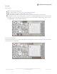
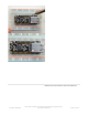

Classic SPI Pins:
SCK - SPI Clock from your microcontroller, level shifted so can be 3-5V logic
MISO - SPI Data
from
the AirLift
to
the microcontroller, this is 3.3V logic out, can be read by 3-5V logic. This is tri-
stated when not selected, so you can share the SPI bus with other devices.
MOSI- SPI Data
to
the AirLift
from
the microcontroller, level shifted so can be 3-5V logic
ESPCS - SPI Chip Select from the microcontroller to start sending commands to the AirLift, level shifted so can be
3-5V logic
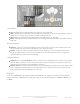
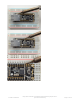
Required Control Pins:
ESPBUSY - this pin is an input from the AirLift, it will let us know when its ready for more commands to be sent.
This is 3.3V logic out, can be read by 3-5V logic. This pin
must
be connected.
ESPRST- this pin is an output to the AirLift. Set low to put the AirLift into reset. You should use this pin, even
though you might be able to run for a short while without it, it's essential to 'kick' the chip if it ever gets into a
locked up state. Level shifted so can be 3-5V logic
Optional Control Pins:
ESPGPIO0 - this is the ESP32 GPIO0 pin, which is used to put it into bootloading mode. It is also used if you like
when the ESP32 is acting as a server, to let you know data is ready for reading. It's not required, you'll need to
solder the pad on the bottom of the FeatherWing to connect it.
ESPRX & ESPTX - Serial data in and Serial data out, used for bootloading new firmware only. Leave disconnected
when not uploading new WiFi firmware to the AirLift (which is a rare occurance). You'll need to solder the two
pads on the bottom of the FeatherWing to use these pins.
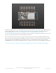
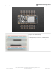
RGB LED
There is a small RGB LED to the left of the ESP32. These RGB LEDs are available in the Arduino and CircuitPython
libraries if you'd like to PWM them for a visual alert. They're connected to the ESP32's pins 26 (Red), 25 (Green), and
27 (Blue).
© Adafruit Industries
https://learn.adafruit.com/adafruit-airlift-featherwing-esp32-wifi-co-
processor-featherwing
Page 7 of 39