
Datasheet


Version: A00 Document No.: SJ-GU-TFmini-01 Page 9 of 10
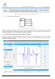
Fig. 5 Client Interface of Distance Measurement Demonstration in Windows
① Serial transmission port and baud rate selections: Plug in TTL-USB adapter plate, select the
corresponding port number and baud rate, and click the “CONNECT” button to establish the
connection;
② Mode selection: It is the special mode specified for Pix version of TF01 and TF02 products, which is
not provided on TF_mini;
③ Pause button: Click it to pause the upper computer for analysis on the images in ⑧; “AMB” is used for
the internal debugging under special cases and cannot be set in any case;
④ Measurement range area selection: Click 5m or 20m, the range scale in area ⑨ will be adjusted to the
corresponding value.
⑤ Data average: The default value is 5; that is, the values of every 5 points accepted by the upper
computer are averaged and output at a point value. After modified, the command will be sent with
“Enter” key on the keyboard;
⑥ Serial port command sending area: This window is used to send hexadecimal TF serial port command
and modify or set the function;
⑦ Data recording bar. This text window is used to name the data to be saved; after the name is input, press
“Enter” key to record TF data by clicking “RECORD” button and end the record by clicking the button
again; the folder with saved data can be opened by clicking “FOLDER” button;
⑧ Data image display area: the upper computer can draw a continuous ranging image with the received
data;
⑨ Measurement range scale: Display the real-time detection distance value;
⑩ Data display area: Dist indicates the distance detection value in mm; EffectivePoint indicates the total
effective data output by TF; Strength indicates the signal strength, under the pix mode, Strength is
defaulted as 0 because there is no strength input.
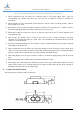
8. Product Size Specifications
The following is the module outline size drawing.
Benewake (Beijing) Co. Ltd.