
Datasheet
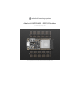


GND - this is the common ground for all power and logic
BAT - this is the positive voltage to/from the JST jack for the optional Lipoly battery
USB - this is the positive voltage to/from the micro USB jack if connected
EN - this is the 3.3V regulator's enable pin. It's pulled up, so connect to ground to disable the 3.3V regulator
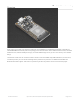
3V - this is the output from the 3.3V regulator. The regulator can supply 500mA peak but half of that is drawn by
the ESP32, and it's a fairly power-hungry chip. So if you need a ton of power for stuff like LEDs, motors, etc. Use
the USB or BAT pins, and an additional regulator
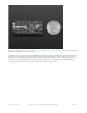
Logic pins
This is the general purpose I/O pin set for the microcontroller. All logic is 3.3V
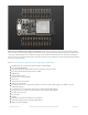
Serial pins
RX and TX are the additional Serial1 pins, and are
not
connected to the USB/Serial converter. That means you can use
them to connect to UART-devices like GPS's, fingerprint sensors, etc.
The TX pin is the output
from
the module. The RX pin is the input
into
the module. Both are 3.3V logic
I2C & SPI pins
You can use the ESP32 to control I2C and SPI devices, sensors, outputs, etc. If using with Arduino, the standard Wire
and SPI devices work as you'd expect!
The ESP32 runs on 3.3V power and logic, and unless otherwise specified, GPIO pins are not 5V safe!
© Adafruit Industries https://learn.adafruit.com/adafruit-huzzah32-esp32-feather Page 8 of 27