
Datasheet
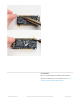

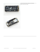

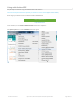


The above shows the Micro USB jack (left), Lipoly JST jack (top left), as well as the 3.3V regulator (to the right of the
JST jack), changeover diode+transistor (below the JST jack) and the Lipoly charging circuitry (right below the
regulator).
There's also a CHG LED next to the USB jack, which will light up while the battery is charging. This LED might also
flicker if the battery is not connected, it's normal.
Power supplies
You have a lot of power supply options here! We bring out the BAT pin, which is tied to the lipoly JST connector, as
well as USB which is the +5V from USB if connected. We also have the 3V pin which has the output from the 3.3V
regulator. We use a 500mA peak low-dropout regulator. Please budget 250mA for the WROOM32 module. While you
can get 500mA total from it, you can't do it continuously from 5V as it will overheat the regulator. We use this to power
the ESP32 which draws about 200mA continuous. The good news is you can put the ESP32 into sleep and low-power
modes much easier.
Measuring Battery
If you're running off of a battery, chances are you wanna know what the voltage is at! That way you can tell when the
battery needs recharging. Lipoly batteries are 'maxed out' at 4.2V and stick around 3.7V for much of the battery life,
then slowly sink down to 3.2V or so before the protection circuitry cuts it off. By measuring the voltage you can quickly
tell when you're heading below 3.7V
© Adafruit Industries https://learn.adafruit.com/adafruit-huzzah32-esp32-feather Page 22 of 27