
Datasheet

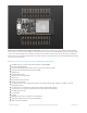


A3 - this is an analog input A3 and also GPI #39. Note it is
not
an output-capable pin! It uses ADC #1
A4 - this is an analog input A4 and also GPI #36. Note it is
not
an output-capable pin! It uses ADC #1
A5 - this is an analog input A5 and also GPIO #4. It uses ADC #2
21 - General purpose IO pin #21
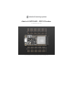
Top row:
13 - This is GPIO #13 and also an analog input A12 on ADC #1. It's also connected to the red LED next to the USB
port
12 - This is GPIO #12 and also an analog input A11 on ADC #2. This pin has a pull-down resistor built into it, we
recommend using it as an output only, or making sure that the pull-down is not affected during boot.
27 - This is GPIO #27 and also an analog input A10 on ADC #2
33 - This is GPIO #33 and also an analog input A9 on ADC #1. It can also be used to connect a 32 KHz crystal.
15 - This is GPIO #15 and also an analog input A8 on ADC #2
32 - This is GPIO #32 and also an analog input A7 on ADC #1. It can also be used to connect a 32 KHz crystal.
14 - This is GPIO #14 and also an analog input A6 on ADC #2
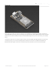
There's also an external analog input
A13 - This is general purpose input #35 and also an analog input A13, which is a resistor divider connected to the
VBAT line
Note you can only read analog inputs on ADC #1 once WiFi has started
© Adafruit Industries https://learn.adafruit.com/adafruit-huzzah32-esp32-feather Page 10 of 27