
Datasheet


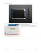


1.8" TFT Breakout
This color display uses SPI to receive image data. That means you need at least 4 pins - clock, data in, tft cs and d/c. If
you'd like to have SD card usage too, add another 2 pins - data out and card cs. However, there's a couple other pins
you may want to use, lets go thru them all!
Lite - this is the PWM input for the backlight control. Connect to 3-5VDC to turn on the backlight. Connect to
ground to turn it off. Or, you can PWM at any frequency.
MISO - this is the SPI Master In Slave Out pin, its used for the SD card. It isn't used for the TFT display which is
write-only
SCLK - this is the SPI clock input pin
MOSI - this is the SPI Master Out Slave In pin, it is used to send data from the microcontroller to the SD card
and/or TFT
TFT_CS - this is the TFT SPI chip select pin
Card CS - this is the SD card chip select, used if you want to read from the SD card.
D/C - this is the TFT SPI data or command selector pin
RST - this is the TFT reset pin. Connect to ground to reset the TFT! Its best to have this pin controlled by the
library so the display is reset cleanly, but you can also connect it to the Arduino Reset pin, which works for most
cases.
Vcc - this is the power pin, connect to 3-5VDC - it has reverse polarity protection but try to wire it right!
GND - this is the power and signal ground pin
For the level shifter we use the CD74HC4050 (https://adafru.it/Boj) which has a typical propagation delay of ~10ns
© Adafruit Industries https://learn.adafruit.com/1-8-tft-display Page 5 of 36