
Datasheet


All the GPIO pads can be used as digital inputs, digital outputs, for LEDs, buttons and switches. In additon, all can be
used as analog inputs (12-bit ADC) or hardware capacitive touch. All pads can also be used as hardware interrupts
inputs.
Each pad can provide up to ~7mA of current. Don't connect a motor or other high-power component directly to the
pins! Instead, use a transistor to power the DC motor on/off (https://adafru.it/aUD)
On a Gemma M0, the GPIO are 3.3V output level, and should not be used with 5V inputs. In general, most 5V devices
are OK with 3.3V output though.
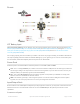
The three pads are completely 'free' pins, they are not used by the USB connection, LEDs, DotStar, etc so you never
have to worry about the USB interface interfering with them when programming
Unique pad capabilities
Pad #0 / A2 - this is connected to PA04 on the ATSAMD21. This pin can be used as a digital I/O with selectable
pullup or pulldown, capacitive touch, analog input (use 'A2'), PWM output, and is also used for I2C data (SDA),
and hardware Serial RX.
Pad #1 / A0 - this is connected to PA02 on the ATSAMD21. This pin can be used as a digital I/O with selectable
pullup or pulldown, capacitive touch, analog input (use 'A0'), and true analog (10-bit DAC) output. It cannot be
used as PWM output.
Pad #2 / A1 - this is connected to PA05 on the ATSAMD21. This pin can be used as a digital I/O with selectable
pullup or pulldown, capacitive touch, analog input (use 'A1'), PWM output, and is also used for I2C clock (SCL),
and hardware Serial TX.
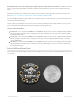
Secret SWD and Reset Pads
On the bottom of the Gemma M0 you will see three small pads. These are used for our programming/test but you can
use them too.
© Adafruit Industries https://learn.adafruit.com/adafruit-gemma-m0 Page 14 of 186