
User Manual


this is hard-wired to digital pins 11 and 13, but on some Feather boards these physical pins have different numeric
assignments, and standalone (non-FeatherWing) matrices are free to use other pins. See the dotstar_wing.ino example
for pin assignments on other boards.
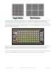
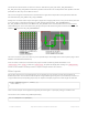
The next argument is the interesting one. This indicates where the first pixel in the matrix is positioned and the
arrangement of rows or columns. The first pixel must be at one of the four corners;
which
corner is indicated by adding
either DS_MATRIX_TOP or DS_MATRIX_BOTTOM to either DS_MATRIX_LEFT or DS_MATRIX_RIGHT. The
row/column arrangement is indicated by further adding either DS_MATRIX_COLUMNS or DS_MATRIX_ROWS to
either DS_MATRIX_PROGRESSIVE or DS_MATRIX_ZIGZAG. These values are all added to form a single value as in
the above code.
DS_MATRIX_TOP + DS_MATRIX_LEFT +
DS_MATRIX_COLUMNS + DS_MATRIX_PROGRESSIVE
The last argument is exactly the same as with the DotStar library, indicating the type of LED pixels being used. In some
cases you can simply leave this argument off.
The point of this setup is that the rest of the sketch never needs to think about the layout of the matrix. Coordinate
(0,0) for drawing graphics will always be at the top-left for you, regardless of the actual position of the first DotStar.
Why not just use the rotation feature in Adafruit_GFX?
© Adafruit Industries https://learn.adafruit.com/adafruit-dotstar-leds Page 40 of 48