
User Manual

Arduino Library Use
Doxygen-generated documentation for the Adafruit_DotStar library is available here. (https://adafru.it/Etq)
It’s assumed at this point that you have the Adafruit_DotStar library for Arduino installed and have run the strandtest
example sketch successfully. If not, return to the prior page for directions to set that up.
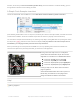
To learn about writing your own DotStar sketches, let’s begin by dissecting the strandtest sketch…
All DotStar sketches begin by including the header file:
Just below this in the strandtest example are some extra lines that are sometimes needed…
Most microcontrollers have some kind of SPI bus (a high-speed serial interface to devices). If so, there’s an SPI-related
header file that must be included. But a few microcontrollers (such as the diminutive Adafruit Gemma and Trinket) don’t
have SPI, in which case that line should be commented out (preceded with a “//”) or simply deleted.
Speaking of Gemma and Trinket…the next line, normally commented out, should be enabled (remove the “//”) if using
one of those boards.
The next few lines define the length of the strip (30 pixels in our example, but you can change this to more or less to
match your setup) and which pins to use for the data and clock signals. The wiring diagrams previously shown had
these on 4 and 5…but they can usually be any two pins, whatever works best for you and matches your wiring:
This is how we declare a DotStar
object.
We’ll refer to this by name later to control the strip of pixels.
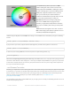
The last parameter is optional — this is the color data order of the DotStar strip, which has changed over time in
different production runs. Default is DOTSTAR_BRG, so change this if you have an earlier strip. If the LEDs are basically
working but coming up the wrong colors, this is usually the reason why…swap around the R, G and B until things look
right.
If using an SPI-capable microcontroller, this usually provides better performance. However, this must be wired to
specific pins, and it varies among microcontrollers. For example, on the Arduino Uno the SPI MOSI and SCK signals
are on pins 11 and 13 respectively. You’ll need a pinout diagram for other boards, look for the SPI MOSI and SCK pins!
The object declaration in this case is a little different…simply leave out the data and clock pin numbers:
#include <Adafruit_DotStar.h>
// Because conditional #includes don't work w/Arduino sketches...
#include <SPI.h> // COMMENT OUT THIS LINE FOR GEMMA OR TRINKET
//#include <avr/power.h> // ENABLE THIS LINE FOR GEMMA OR TRINKET
#define NUMPIXELS 30 // Number of LEDs in strip
// Here's how to control the LEDs from any two pins:
#define DATAPIN 4
#define CLOCKPIN 5
Adafruit_DotStar strip(NUMPIXELS, DATAPIN, CLOCKPIN, DOTSTAR_BRG);
© Adafruit Industries https://learn.adafruit.com/adafruit-dotstar-leds Page 27 of 48