Adafruit 16-Channel PWM/Servo HAT & Bonnet for Raspberry Pi Created by lady ada Last updated on 2019-01-09 10:08:07 PM UTC
Guide Contents Guide Contents Overview Powering Servos Powering Servos / PWM 2 4 6 6 OR Current Draw Requirements Adding a Capacitor to the thru-hole capacitor slot 7 7 8 Connecting Servos 10 Connecting a Servo Adding More Servos 10 11 Attach & Test HAT/Bonnet Step 1 - Plug in HAT Step 2.
Schematics and Fab Print for Pi Servo Bonnet © Adafruit Industries https://learn.adafruit.
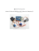
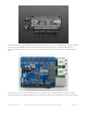
Overview The Raspberry Pi is a wonderful little computer, but one thing it isn't very good at is controlling DC Servo Motors - these motors need very specific and repetitive timing pulses to set the position. Instead of asking the Pi Linux kernel to send these signals, pop on our handy HAT or Bonnet. These boards add the capability to control 16 Servos with perfect timing. They can also do PWM up to 1.6 KHz with 12 bit precision, all completely free-running.
The Adafruit 16-Channel 12-bit PWM/Servo HAT or Bonnet will drive up to 16 servos or PWM outputs over I2C with only 2 pins. The on-board PWM controller will drive all 16 channels simultaneously with no additional Raspberry Pi processing overhead. What's more, you can stack up to 62 of them to control up to 992 servos - all with the same 2 pins! Best of all, we even have a Python library you can use, so you'll be up and running instantly, to make your robotic creation com to life.
Powering Servos The power input section of the HAT and Bonnet are both on the left hand side. The HAT has both 2.1mm DC jack and a terminal block The Bonnet has a spot for either DC jack or terminal block Powering Servos / PWM The drivers have two power supplies. One is VCC - that is the 3.3V power from the Raspberry Pi, it is used to power the PWM chip and determines the I2C logic level and the PWM signal logic level.
Use either a 5V wall adapter, 2 Amp+ is recommended OR Or, for portable use, a 4 or 5 x AA battery pack can be connected to the terminal block. Current Draw Requirements Nearly all servos are designed to run on about 5 or 6v. Keep in mind that a lot of servos moving at the same time (particularly large powerful ones) will need a lot of current. Even micro servos will draw several hundred mA when moving. Some High-torque servos will draw more than 1A each under load.
SERVOS CAN USE A LOT OF POWER! It is not a good idea to use the Raspberry Pi's 5v pin to power your servos! Electrical noise and 'brownouts' from excess current draw could cause your Pi to act erratically, reset and/or overheat. Seriously, keep the Pi power supply and the Servo power supply completely seperate! Adding a Capacitor to the thru-hole capacitor slot We have a spot on the PCB for soldering in an electrolytic capacitor. Based on your usage, you may or may not need a capacitor.
© Adafruit Industries https://learn.adafruit.
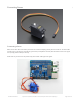
Connecting Servos Connecting a Servo Most servos come with a standard 3-pin female connector that will plug directly into the headers on the Servo HAT headers. Be sure to align the plug with the ground wire (usually black or brown) with the bottom row and the signal wire (usually yellow or white) on the top. Works with any servo that can be powered by 5V and take 3.3V logic level signals. © Adafruit Industries https://learn.adafruit.
Adding More Servos Up to 16 servos can be attached to one board. If you need to control more than 16 servos, additional boards can be stacked as described on the next page. © Adafruit Industries https://learn.adafruit.
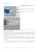
Attach & Test HAT/Bonnet Step 1 - Plug in HAT Now you have soldered the HAT up and you know how to power the servos, we can install the HAT Begin by having the Pi shutdown and not powered, plug the HAT on top to match the 2x20 headers, and power up the Pi Step 2. Configure your Pi to use I2C devices To learn more about how to setup I2C with either Raspbian or Occidentalis, please take a minor diversion to this Adafruit Tutorial: http://learn.adafruit.
This will search /dev/i2c-1 for all address, and if an Adafruit PWM/Servo HAT is properly connected and it's set to its default address -- meaning none of the 6 address solder jumpers at the top of the board have been soldered shut -- it should show up at 0x40 (binary 1000000) as follows: Once both of these packages have been installed, and i2cdetect finds the 0x40 I2C address, you have everything you need to get started accessing I2C and SMBus devices in Python. © Adafruit Industries https://learn.
Python Usage It's easy to control PWM or servos with the Adafruit 16-channel PWM/Servo HAT and Bonnet. There are multiple CircuitPython libraries available to work with the different features of these boards including Adafruit CircuitPython PCA9685 (https://adafru.it/tZF), and Adafruit CircuitPython ServoKit (https://adafru.it/Dpu). These libraries make it easy to write Python code to control PWM and servo motors. Python Wiring First assemble the HAT or Bonnet exactly as shown in the previous pages.
Dimming LEDs This HAT and Bonnet use the PCA9685. Each channel of the HAT and Bonnet can be used to control the brightness of an LED. The PCA9685 generates a high-speed PWM signal which turns the LED on and off very quickly. If the LED is turned on longer than turned off it will appear brighter to your eyes. First you'll need to import the necessary modules, initialize the I2C bus for your board, and create an instance of the class. import board import busio import adafruit_pca9685 i2c = busio.I2C(board.
led_channel.duty_cycle = 1000 You should see the LED dimly lit. Try experimenting with other duty cycle values to see how the LED changes brightness! For example make the LED glow on and off by setting duty_cycle in a loop: # Increase brightness: for i in range(0xffff): led_channel.duty_cycle = i # Decrease brightness: for i in range(0xffff, 0, -1): led_channel.duty_cycle = i These for loops take a while because 16-bits is a lot of numbers. CTRL-C to stop the loop from running and return to the REPL.
range. The default is 180 degrees but your servo may have a smaller sweep. You can change the total angle by setting actuation_range . For example, to set the actuation range to 160 degrees: kit.servo[0].actuation_range = 160 Often the range an individual servo recognises varies a bit from other servos. If the servo didn't sweep the full expected range, then try adjusting the minimum and maximum pulse widths using set_pulse_width_range(min_pulse, max_pulse) .
"""Simple test for a standard servo on channel 0 and a continuous rotation servo on channel 1.""" import time from adafruit_servokit import ServoKit # Set channels to the number of servo channels on your kit. # 8 for FeatherWing, 16 for Shield/HAT/Bonnet. kit = ServoKit(channels=8) kit.servo[0].angle = 180 kit.continuous_servo[1].throttle = 1 time.sleep(1) kit.continuous_servo[1].throttle = -1 time.sleep(1) kit.servo[0].angle = 0 kit.continuous_servo[1].throttle = 0 © Adafruit Industries https://learn.
Library Reference The driver consists of the following functions, which you can use to drive the underlying hardware when writing your own application in Python: Initialize Object You can create a new object for each HAT with pwm = PWM(0x40) In this case, pwm (lowercase) is the object created, and PWM(0x40) is the creation call. By default, all HATs are address 0x40, but by changing the address jumpers, you can create objects that use other addresses such as 0x60, 0x42, etc.
The following example will cause channel 15 to start low, go high around 25% into the pulse (tick 1024 out of 4096), transition back to low 75% into the pulse (tick 3072), and remain low for the last 25% of the pulse: pwm.setPWM(15, 1024, 3072) If you need to calculate pulse-width in microseconds, you can do that by first figuring out how long each cycle is. That would be 1/freq where freq is the PWM frequency you set above. For 1000 Hz, that would be 1 millisecond.
Stacking HATs Even though HATs are not intended to be stacked, you can stack up to 62 HATs and not have an address collision, for up to 992 PWM outputs! You'll still need to provide power and write code for all those outputs but they can all share the same SDA/SCL pins no problem. You will need to have installed stacking headers & right angle 3x4 connections for it to physically connect. Extra Parts If you want to stack HATs on top of this one, make sure you pick up a HAT-stacking header (https://adafru.
You'll also need a set of right-angle 3x4 headers, since you will have to have the servo connections stick out instead of up © Adafruit Industries https://learn.adafruit.
Addressing the HATs Each HAT in the stack must be assigned a unique address. This is done with the address jumpers on the middle right of the board. The I2C base address for each board is 0x40. The binary address that you program with the address jumpers is added to the base I2C address. To program the address offset, use a drop of solder to bridge the corresponding address jumper for each binary '1' in © Adafruit Industries https://learn.adafruit.
the address. This photo is from the Arduino Shield version of this driver but its the same setup Board 0: Address = 0x40 Offset = binary 00000 (no jumpers required) Board 1: Address = 0x41 Offset = binary 00001 (bridge A0 as in the photo above) Board 2: Address = 0x42 Offset = binary 00010 (bridge A1) Board 3: Address = 0x43 Offset = binary 00011 (bridge A0 & A1) Board 4: Address = 0x44 Offset = binary 00100 (bridge A2) etc. © Adafruit Industries https://learn.adafruit.
FAQ Can this HAT be used for LEDs or just servos? It can be used for LEDs as well as any other PWM-able device! Use the Signal and Ground pins if you dont mind the LEDs powered by 3.3V and 220ohm series resistor.
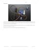
Downloads Files & Downloads Datasheet for servo/PWM control chip PCA9685 (https://adafru.it/emJ) Full Official Specifications for Pi HAT dimensions (https://adafru.it/oNf) EagleCAD PCB files on GitHub (https://adafru.it/oNA) Fritzing object in Adafruit Frizting Library (https://adafru.it/aP3) Schematics Pi HAT and GPIO Breakout: Motor Control Section: Fabrication Print Dimensions in Inches. For more dimensional details, see the official Pi HAT mechanical specification (https://adafru.it/oNf).
Schematics and Fab Print for Pi Servo Bonnet © Adafruit Industries https://learn.adafruit.
© Adafruit Industries Last Updated: 2019-01-09 10:08:06 PM UTC Page 28 of 28