
Datasheet
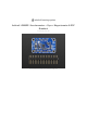


Pinouts
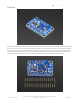
Power Pins
The sensor on the breakout requires 3V power. Since many customers have 5V microcontrollers like Arduino, we
tossed a 3.3V regulator on the board. Its ultra-low dropout so you can power it from 3.3V-5V just fine.
Vin - this is the power pin. Since the chip uses 3 VDC, we have included a voltage regulator on board that will
take 3-5VDC and safely convert it down. To power the board, give it the same power as the logic level of your
microcontroller - e.g. for a 5V micro like Arduino, use 5V
3V3 - this is the 3.3V output from the voltage regulator, you can grab up to 100mA from this if you like
GND - common ground for power and logic
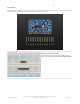
I2C Pins
SCL - I2C clock pin, connect to your microcontrollers I2C clock line. This pin is level shifted so you can use 3-5V
logic, and there's a 10K pullup on this pin.
SDA - I2C data pin, connect to your microcontrollers I2C data line. This pin is level shifted so you can use 3-5V
logic, and there's a 10K pullup on this pin.
SPI Pins
If you're interested in using SPI to interface with the LSM9DS1, you can!
SCL - this is also the SPI clock pin, it's level shifted so you can use 3-5V logic input
SDA - this is also the SPI MOSI pin, it's level shifted so you can use 3-5V logic input
CSAG - this is the Accelerometer+Gyro subchip Chip Select, it's level shifted so you can use 3-5V logic input
CSM - this is the Magnetometer subchip Select, it's level shifted so you can use 3-5V logic input
SDOAG - this is the Accelerometer+Gyro subchip MISO pin - it's 3V logic out, but can be read properly by 5V
logic chips.
SDOM - this is the Magnetometer subchip MISO pin - it's 3V logic out, but can be read properly by 5V logic chips.
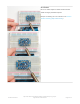
Interrupt & Misc Pins
© Adafruit Industries
https://learn.adafruit.com/adafruit-lsm9ds1-accelerometer-plus-gyro-plus-
magnetometer-9-dof-breakout
Page 5 of 23