
User Manual


Test Drive
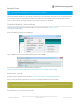
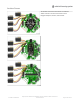
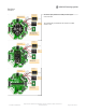
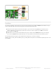
Lets start by controlling a drive output. You'll need to plug something into the 5V and DRIVE1 terminal blocks. I'm just
using a simple LED with resistor but anything that can be powered by 5V will work.
Note that the drive outputs cannot have 5V output so you must connect the positive pin of whatever you're
driving to 5V. Don't try connecting the positive pin to the drive, and the negative pin to GND, it wont work!
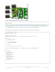
Drive outputs are PWM-able!
PWM values can be anywhere between 0 (0% duty cycle or always off) and 65535 (100% duty cycle or always
on). A value of 32768 would be 50% duty cycle, or on for half of the period and then off for half the period.
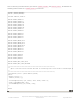
This example will show turning the drive output fully on and off once a second. The macros
CRICKIT_DUTY_CYCLE_OFF and CRICKIT_DUTY_CYCLE_MAX correspond to 0 and 65535 respectively and are used
for readability:
© Adafruit Industries
https://learn.adafruit.com/adafruit-crickit-creative-robotic-interactive-
construction-kit
Page 176 of 201