
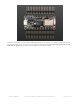
Datasheet

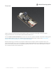
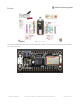


Power Pins
GND - this is the common ground for all power and logic
BAT - this is the positive voltage to/from the JST jack for the optional Lipoly battery
USB - this is the positive voltage to/from the micro USB jack if connected
EN - this is the 3.3V regulator's enable pin. It's pulled up, so connect to ground to disable the 3.3V regulator
3V - this is the output from the 3.3V regulator, it can supply 500mA peak
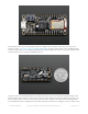
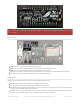
Logic pins
This is the general purpose I/O pin set for the microcontroller. All logic is 3.3V
#0 / RX - GPIO #0, also receive (input) pin for Serial1 and Interrupt #2
#1 / TX - GPIO #1, also transmit (output) pin for Serial1 and Interrupt #3
#2 / SDA - GPIO #2, also the I2C (Wire) data pin. There's no pull up on this pin by default so when using with I2C,
you may need a 2.2K-10K pullup. Also Interrupt #1
#3 / SCL - GPIO #3, also the I2C (Wire) clock pin. There's no pull up on this pin by default so when using with I2C,
you may need a 2.2K-10K pullup. Can also do PWM output and act as Interrupt #0.
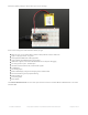
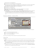
The DFU pin is accidentally labeled GND on the bottom, sorry about that! it should be labeled DFU, dont use it
as a GND
© Adafruit Industries https://learn.adafruit.com/adafruit-feather-32u4-bluefruit-le Page 14 of 211