
Datasheet
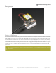


The above shows the Micro USB jack (left), Lipoly JST jack (top left), as well as the 3.3V regulator and changeover
diode (just to the right of the JST jack) and the Lipoly charging circuitry (to the right of the Reset button). There's also a
CHG LED, which will light up while the battery is charging. This LED might also flicker if the battery is not connected.
Power supplies
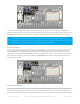
You have a lot of power supply options here! We bring out the BAT pin, which is tied to the lipoly JST connector, as
well as USB which is the +5V from USB if connected. We also have the 3V pin which has the output from the 3.3V
regulator. We use a 500mA peak SPX3819. While you can get 500mA from it, you can't do it continuously from 5V as it
will overheat the regulator. It's fine for, say, powering an ESP8266 WiFi chip or XBee radio though, since the current
draw is 'spiky' & sporadic.
Measuring Battery
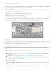
If you're running off of a battery, chances are you wanna know what the voltage is at! That way you can tell when the
battery needs recharging. Lipoly batteries are 'maxed out' at 4.2V and stick around 3.7V for much of the battery life,
then slowly sink down to 3.2V or so before the protection circuitry cuts it off. By measuring the voltage you can quickly
The charge LED is automatically driven by the Lipoly charger circuit. It will try to detect a battery and is
expecting one to be attached. If there isn't one it may flicker once in a while when you use power because it's
trying to charge a (non-existant) battery. It's not harmful, and its totally normal!
© Adafruit Industries https://learn.adafruit.com/adafruit-feather-32u4-bluefruit-le Page 28 of 211