Adafruit Feather 32u4 Bluefruit LE Created by lady ada Last updated on 2019-11-15 12:42:04 AM UTC
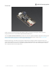
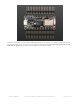
Overview Feather is the new development board from Adafruit, and like it's namesake it is thin, light, and lets you fly! We designed Feather to be a new standard for portable microcontroller cores. This is the Adafruit Feather 32u4 Bluefruit - our take on an 'all-in-one' Arduino-compatible + Bluetooth Low Energy with built in USB and battery charging. Its an Adafruit Feather 32u4 with a BTLE module, ready to rock! We have other boards in the Feather family, check'em out here (https://adafru.
At the Feather 32u4's heart is at ATmega32u4 clocked at 8 MHz and at 3.3V logic, a chip setup we've had tons of experience with as it's the same as the Flora (https://adafru.it/dVl). This chip has 32K of flash and 2K of RAM, with built in USB so not only does it have a USB-to-Serial program & debug capability built in with no need for an FTDI-like chip, it can also act like a mouse, keyboard, USB MIDI device, etc. To make it easy to use for portable projects, we added a connector for any of our 3.
monitor the battery voltage to detect when you need a recharge. Here's some handy specs! Like all Feather 32u4's you get: Measures 2.0" x 0.9" x 0.28" (51mm x 23mm x 8mm) without headers soldered in Light as a (large?) feather - 5.7 grams ATmega32u4 @ 8MHz with 3.3V logic/power 3.
The Power of Bluefruit LE The Bluefruit LE module is an nRF51822 chipset from Nordic, programmed with multi-function code that can do quite a lot! For most people, they'll be very happy to use the standard Nordic UART RX/TX connection profile. In this profile, the Bluefruit acts as a data pipe, that can 'transparently' transmit back and forth from your iOS or Android device. You can use our iOS App (https://adafru.it/iCi) or Android App (https://adafru.
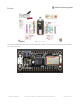
Comes fully assembled and tested, with a USB bootloader that lets you quickly use it with the Arduino IDE. We also toss in some header so you can solder it in and plug into a solderless breadboard. Lipoly battery, MicroSD card and USB cable not included (but we do have lots of options in the shop if you'd like!) © Adafruit Industries https://learn.adafruit.
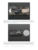
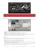
Pinouts The Feather 32u4 Bluefruit LE is chock-full of microcontroller goodness. There's also a lot of pins and ports. We'll take you a tour of them now! © Adafruit Industries https://learn.adafruit.
The DFU pin is accidentally labeled GND on the bottom, sorry about that! it should be labeled DFU, dont use it as a GND Power Pins GND - this is the common ground for all power and logic BAT - this is the positive voltage to/from the JST jack for the optional Lipoly battery USB - this is the positive voltage to/from the micro USB jack if connected EN - this is the 3.3V regulator's enable pin. It's pulled up, so connect to ground to disable the 3.3V regulator 3V - this is the output from the 3.
#5 - GPIO #5, can also do PWM output #6 - GPIO #6, can also do PWM output and analog input A7 #9 - GPIO #9, also analog input A9 and can do PWM output. This analog input is connected to a voltage divider for the lipoly battery so be aware that this pin naturally 'sits' at around 2VDC due to the resistor divider #10 - GPIO #10, also analog input A10 and can do PWM output. #11 - GPIO #11, can do PWM output.
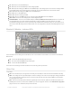
Bottom Side On the back we also have SWDIO/SWCLK/RESET pins, these are used for programming the Bluefruit LE module itself.
Assembly We ship Feathers fully tested but without headers attached - this gives you the most flexibility on choosing how to use and configure your Feather Header Options! Before you go gung-ho on soldering, there's a few options to consider! The first option is soldering in plain male headers, this lets you plug in the Feather into a solderless breadboard © Adafruit Industries https://learn.adafruit.
Another option is to go with socket female headers. This won't let you plug the Feather into a breadboard but it will let you attach featherwings very easily © Adafruit Industries https://learn.adafruit.
We also have 'slim' versions of the female headers, that are a little shorter and give a more compact shape © Adafruit Industries https://learn.adafruit.
Finally, there's the "Stacking Header" option. This one is sort of the best-of-both-worlds. You get the ability to plug into a solderless breadboard and plug a featherwing on top. But its a little bulky Soldering in Plain Headers Prepare the header strip: Cut the strip to length if necessary. It will be easier to solder if you insert it into a breadboard - long pins down © Adafruit Industries https://learn.adafruit.
Add the breakout board: Place the breakout board over the pins so that the short pins poke through the breakout pads And Solder! Be sure to solder all pins for reliable electrical contact. (For tips on soldering, be sure to check out our Guide to Excellent Soldering (https://adafru.it/aTk)). © Adafruit Industries https://learn.adafruit.
Solder the other strip as well. © Adafruit Industries https://learn.adafruit.
You're done! Check your solder joints visually and continue onto the next steps Soldering on Female Header Tape In Place For sockets you'll want to tape them in place so when you flip over the board they don't fall out © Adafruit Industries https://learn.adafruit.
Flip & Tack Solder After flipping over, solder one or two points on each strip, to 'tack' the header in place © Adafruit Industries https://learn.adafruit.
And Solder! Be sure to solder all pins for reliable electrical contact. (For tips on soldering, be sure to check out our Guide to Excellent Soldering (https://adafru.it/aTk)). © Adafruit Industries https://learn.adafruit.
You're done! Check your solder joints visually and continue onto the next steps © Adafruit Industries https://learn.adafruit.
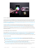
Power Management Battery + USB Power We wanted to make the Feather easy to power both when connected to a computer as well as via battery. There's two ways to power a Feather. You can connect with a MicroUSB cable (just plug into the jack) and the Feather will regulate the 5V USB down to 3.3V. You can also connect a 4.2/3.7V Lithium Polymer (Lipo/Lipoly) or Lithium Ion (LiIon) battery to the JST jack. This will let the Feather run on a rechargable battery.
The above shows the Micro USB jack (left), Lipoly JST jack (top left), as well as the 3.3V regulator and changeover diode (just to the right of the JST jack) and the Lipoly charging circuitry (to the right of the Reset button). There's also a CHG LED, which will light up while the battery is charging. This LED might also flicker if the battery is not connected. The charge LED is automatically driven by the Lipoly charger circuit. It will try to detect a battery and is expecting one to be attached.
tell when you're heading below 3.7V To make this easy we stuck a double-100K resistor divider on the BAT pin, and connected it to D9 (a.k.a analog #9 A9). You can read this pin's voltage, then double it, to get the battery voltage. #define VBATPIN A9 float measuredvbat = analogRead(VBATPIN); measuredvbat *= 2; // we divided by 2, so multiply back measuredvbat *= 3.3; // Multiply by 3.3V, our reference voltage measuredvbat /= 1024; // convert to voltage Serial.print("VBat: " ); Serial.
there's no way to disable the charger Do not use 7.4V RC batteries on the battery port - this will destroy the board The Feather is not designed for external power supplies - this is a design decision to make the board compact and low cost. It is not recommended, but technically possible: Connect an external 3.3V power supply to the 3V and GND pins. Not recommended, this may cause unexpected behavior and the EN pin will no longer.
Arduino IDE Setup The first thing you will need to do is to download the latest release of the Arduino IDE. You will need to be using version 1.8 or higher for this guide https://adafru.it/f1P https://adafru.it/f1P After you have downloaded and installed the latest version of Arduino IDE, you will need to start the IDE and navigate to the Preferences menu. You can access it from the File menu in Windows or Linux, or the Arduino menu on OS X. A dialog will pop up just like the one shown below.
We will be adding a URL to the new Additional Boards Manager URLs option. The list of URLs is comma separated, and you will only have to add each URL once. New Adafruit boards and updates to existing boards will automatically be picked up by the Board Manager each time it is opened. The URLs point to index files that the Board Manager uses to build the list of available & installed boards.
Here's a short description of each of the Adafruit supplied packages that will be available in the Board Manager when you add the URL: Adafruit AVR Boards - Includes support for Flora, Gemma, Feather 32u4, Trinket, & Trinket Pro.
Using with Arduino IDE Since the Feather 32u4 uses an ATmega32u4 chip running at 8 MHz, you can pretty easily get it working with the Arduino IDE. Many libraries (including the popular ones like NeoPixels and display) work great with the '32u4 and 8 MHz clock speed. Now that you have added the appropriate URLs to the Arduino IDE preferences, you can open the Boards Manager by navigating to the Tools->Board menu.
Install Drivers (Windows Only) When you plug in the Feather, you'll need to possibly install a driver Click below to download our Driver Installer https://adafru.it/AB0 https://adafru.it/AB0 Download and run the installer Run the installer! Since we bundle the SiLabs and FTDI drivers as well, you'll need to click through the license © Adafruit Industries https://learn.adafruit.
Select which drivers you want to install: Click Install to do the installin' Blink Now you can upload your first blink sketch! © Adafruit Industries https://learn.adafruit.
Plug in the Feather 32u4 and wait for it to be recognized by the OS (just takes a few seconds). It will create a serial/COM port, you can now select it from the dropdown, it'll even be 'indicated' as Feather 32u4! Now load up the Blink example // the setup function runs once when you press reset or power the board void setup() { // initialize digital pin 13 as an output.
Don't click the reset button before uploading, unlike other bootloaders you want this one to run at the time Arduino is trying to upload Ubuntu & Linux Issue Fix If you're on Linux, and are seeing multi-second delays connecting to the serial console, or are seeing "AT" and other gibberish when you connect, follow the steps on this page. (https://adafru.it/iOE) © Adafruit Industries https://learn.adafruit.
Installing BLE Library Install the Adafruit nRF51 BLE Library In order to try out our demos, you'll need to download the Adafruit BLE library for the nRF51 based modules such as this one (a.k.a. Adafruit_BluefruitLE_nRF51) You can check out the code here at github, (https://adafru.it/f4V) but its likely easier to just download via the Arduino library manager.
Run first example Lets begin with the beginner project, which we can use to do basic tests. To open the ATCommand sketch, click on the File > Examples > Adafruit_BluefruitLE_nRF51 folder in the Arduino IDE and select atcommand: This will open up a new instance of the example in the IDE, as shown below: Don't upload the sketch yet! You will have to begin by changing the configuration. Go to the second tab labeled BluefruitConfig.h and find these lines © Adafruit Industries https://learn.adafruit.
// SHARED SPI SETTINGS // ---------------------------------------------------------------------------------------------// The following macros declare the pins to use for HW and SW SPI communication. // SCK, MISO and MOSI should be connected to the HW SPI pins on the Uno when // using HW SPI. This should be used with nRF51822 based Bluefruit LE modules // that use SPI (Bluefruit LE SPI Friend).
If all is good you will see Done Uploading in the status bar Uploading to a brand new board/Upload failures If you are uploading for the first time to a new board, or if upload fails, pres the RESET mini button on the Feather 32u4 Bluefruit when you see the Yellow Arrow lit and the Uploading... text in the status bar. When you see the red LED pulsing on and off, you know the bootloader is running. © Adafruit Industries https://learn.adafruit.
Don't click the reset button before uploading, unlike other bootloaders you want this one to run at the time Arduino is trying to upload Run the sketch OK check again that the correct port is selected Then open up the Serial console. You will see the following: © Adafruit Industries https://learn.adafruit.
This sketch starts by doing a factory reset, then querying the BLE radio for details. These details will be useful if you are debugging the radio. If you see the information as above, you're working! (Note that the dates and version numbers may vary) AT command testing Now you can try out some AT commands - check the rest of the learn guide for a full list. We'll just start with AT+HWGETDIETEMP which will return the approximate ambient temperature of the BLE chipset © Adafruit Industries https://learn.
OK now you know how to upload/test/communicate with your Feather 32u4 Bluefruit. Next up we have a bunch of tutorials who can follow for checking out the bluetooth le radio and apps. For all the following examples, we share the same code between various modules so don't forget to make sure you © Adafruit Industries https://learn.adafruit.
have the RESET pin set to 4 in BluefruitConfig.h for each sketch before uploading, and that Hardware SPI mode is selected by checking for /* ...hardware SPI, using SCK/MOSI/MISO hardware SPI pins and then user selected CS/IRQ/RST */ Adafruit_BluefruitLE_SPI ble(BLUEFRUIT_SPI_CS, BLUEFRUIT_SPI_IRQ, BLUEFRUIT_SPI_RST); © Adafruit Industries https://learn.adafruit.
Configuration! Before you start uploading any of the example sketches, you'll need to CONFIGURE the Bluefruit interface there's a lot of options so pay close attention! Which board do you have? There's a few products under the Bluefruit name: If you are using the Bluefruit LE Shield then you have an SPI-connected NRF51822 module. You can use this with Atmega328 (Arduino UNO or compatible), ATmega32u4 (Arduino Leonardo, compatible) or ATSAMD21 (Arduino Zero, compatible) and possibly others.
Feather M0 Bluefruit LE If you have a Feather M0 Bluefruit LE then you have an ATSAMD21 chip with Hardware SPI, CS = 8, IRQ = 7, RST = 4 Bluefruit LE SPI Friend If you have a stand-alone module, you have a bit of flexibility with wiring however we strongly recommend Hardware SPI, CS = 8, IRQ = 7, RST = 4 You can use this with just about any microcontroller with 5 or 6 pins © Adafruit Industries https://learn.adafruit.
Bluefruit LE UART Friend or Flora BLE If you have a stand-alone UART module you have some flexibility with wiring. However we suggest hardware UART if possible. You will likely need to use the flow control CTS pin if you are not using hardware UART.
Common settings: You can set up how much RAM to set aside for a communication buffer and whether you want to have full debug output.
Software SPI Pins If you don't have a hardware SPI port available, you can use any three pins...its a tad slower but very flexible // SOFTWARE SPI SETTINGS #define BLUEFRUIT_SPI_SCK #define BLUEFRUIT_SPI_MISO #define BLUEFRUIT_SPI_MOSI 13 12 11 Refer to the table above to determine whether you have SPI or UART controlled Bluefruits! Select the Serial Bus Once you've configured your pin setup in the BluefruitConfig.h file, you can now check and adapt the example sketch.
constructor: /* ...software SPI, using SCK/MOSI/MISO user-defined SPI pins and then user selected CS/IRQ/RST */ Adafruit_BluefruitLE_SPI ble(BLUEFRUIT_SPI_SCK, BLUEFRUIT_SPI_MISO, BLUEFRUIT_SPI_MOSI, BLUEFRUIT_SPI_CS, BLUEFRUIT_SPI_IRQ, BLUEFRUIT_SPI_RST); © Adafruit Industries https://learn.adafruit.
BLEUart The BLEUart example sketch allows you to send and receive text data between the Arduino and a connected Bluetooth Low Energy Central device on the other end (such as you mobile phone using the Adafruit Bluefruit LE Connect application for Android (https://adafru.it/f4G) or iOS (https://adafru.it/f4H) in UART mode).
Configuration Check the Configuration! page earlier to set up the sketch for Software/Hardware UART or Software/Hardware SPI.
Once you see the request, use the App to connect to the Bluefruit LE module in UART mode so you get the text box on your phone Any text that you type in the box at the top of the Serial Monitor will be sent to the connected phone, and any data sent from the phone will be displayed in the serial monitor: © Adafruit Industries https://learn.adafruit.
You can see the incoming string here in the Adafruit Bluefruit LE Connect app below (iOS in this case): © Adafruit Industries https://learn.adafruit.
The response text ('Why hello, Arduino!') can be seen below: © Adafruit Industries https://learn.adafruit.
© Adafruit Industries https://learn.adafruit.
HIDKeyboard The HIDKeyboard example shows you how you can use the built-in HID keyboard AT commands to send keyboard data to any BLE-enabled Android or iOS phone, or other device that supports BLE HID peripherals. Opening the Sketch To open the ATCommand sketch, click on the File > Examples > Adafruit_BluefruitLE_nRF51 folder in the Arduino IDE and select hidkeyboard: This will open up a new instance of the example in the IDE, as shown below: © Adafruit Industries https://learn.adafruit.
Configuration Check the Configuration! page earlier to set up the sketch for Software/Hardware UART or Software/Hardware SPI.
To send keyboard data, type anything into the textbox at the top of the Serial Monitor and click the Send button. Bonding the HID Keyboard Before you can use the HID keyboard, you will need to 'bond' it to your phone or PC. The bonding process establishes a permanent connection between the two devices, meaning that as soon as your phone or PC sees the Bluefruit LE module again it will automatically connect. © Adafruit Industries https://learn.adafruit.
The exact procedures for bonding the keyboard will varying from one platform to another. When you no longer need a bond, or wish to bond the Bluefruit LE module to another device, be sure to delete the bonding information on the phone or PC, otherwise you may not be able to connect on a new device! Android To bond the keyboard on a Bluetooth Low Energy enabled Android device, go to the Settings application and click the Bluetooth icon. These screenshots are based on Android 5.0 running on a Nexus 7 2013.
To delete the bonding information, click the gear icon to the right of the device name and the click the Forget button: iOS To bond the keyboard on an iOS device, go to the Settings application on your phone, and click the Bluetooth menu item. The keyboard should appear under the OTHER DEVICES list: © Adafruit Industries https://learn.adafruit.
Once the bonding process is complete the device will be moved to the MY DEVICES category, and you can start to use the Bluefruit LE module as a keyboard: To unbond the device, click the 'info' icon and then select the Forget this Device option in the menu: © Adafruit Industries https://learn.adafruit.
OS X To bond the keyboard on an OS X device, go to the Bluetooth Preferences window and click the Pair button beside the Bluefruit Keyboard device generated by this example sketch: To unbond the device once it has been paired, click the small 'x' icon beside Bluefruit Keyboard: © Adafruit Industries https://learn.adafruit.
... and then click the Remove button when the confirmation dialogue box pops up: © Adafruit Industries https://learn.adafruit.
Controller The Controller sketch allows you to turn your BLE-enabled iOS or Android device in a hand-held controller or an external data source, taking advantage of the wealth of sensors on your phone or tablet. You can take accelerometer or quaternion data from your phone, and push it out to your Arduino via BLE, or get the latest GPS co-ordinates for your device without having to purchase (or power!) any external HW.
Configuration Check the Configuration! page earlier to set up the sketch for Software/Hardware UART or Software/Hardware SPI. The default is hardware SPI If using software or hardware Serial UART: This tutorial will also be easier to use if you wire up the MODE pin, you can use any pin but our tutorial has pin 12 by default. You can change this to any pin.
Using Bluefruit LE Connect in Controller Mode Once the sketch is running you can open Adafruit's Bluefruit LE Connect application (available for Android (https://adafru.it/f4G) or iOS (https://adafru.it/f4H)) and use the Controller application to interact with the sketch. (If you're new to Bluefruit LE Connect, have a look at our dedicated Bluefruit LE Connect learning guide (https://adafru.it/iCm).
This will bring up a list of data points you can send from your phone or tablet to your Bluefruit LE module, by enabling or disabling the appropriate sensor(s). Streaming Sensor Data You can take Quaternion (absolute orientation), Accelerometer, Gyroscope, Magnetometer or GPS Location data from your phone and send it directly to your Arduino from the Controller activity.
The data is parsed in the example sketch and output to the Serial Monitor as follows: Accel Accel Accel Accel Accel 0.20 0.22 0.25 0.21 0.27 -0.51 -0.50 -0.51 -0.47 -0.48 -0.76 -0.83 -0.83 -0.76 -0.82 © Adafruit Industries https://learn.adafruit.
Note that even though we only print 2 decimal points, the values are received from the App as a full 4-byte floating point. Control Pad Module You can also use the Control Pad Module to capture button presses and releases by selecting the appropriate menu item: This will bring up the Control Pad panel, shown below: © Adafruit Industries https://learn.adafruit.
Button presses and releases will all be logged to the Serial Monitor with the ID of the button used: Button Button Button Button 8 8 3 3 pressed released pressed released Color Picker Module You can also send RGB color data via the Color Picker module, which presents the following color selection dialogue: © Adafruit Industries https://learn.adafruit.
This will give you Hexadecimal color data in the following format: © Adafruit Industries https://learn.adafruit.
RGB #A42FFF You can combine the color picker and controller sample sketches to make color-configurable animations triggered by buttons in the mobile app-- very handy for wearables! Download this combined sample code (configured for Feather but easy to adapt to FLORA, BLE Micro, etc.) to get started: https://adafru.it/kzF https://adafru.it/kzF © Adafruit Industries https://learn.adafruit.
HeartRateMonitor The HeartRateMonitor example allows you to define a new GATT Service and associated GATT Characteristics, and update the characteristic values using standard AT commands. Opening the Sketch To open the ATCommand sketch, click on the File > Examples > Adafruit_BluefruitLE_nRF51 folder in the Arduino IDE and select heartratemonitor: This will open up a new instance of the example in the IDE, as shown below: © Adafruit Industries https://learn.adafruit.
Configuration Check the Configuration! page earlier to set up the sketch for Software/Hardware UART or Software/Hardware SPI. The default is hardware SPI If Using Hardware or Software UART This tutorial does not need to use the MODE pin, make sure you have the mode switch in CMD mode if you do not configure & connect a MODE pin This demo uses some long data transfer strings, so we recommend defining and connecting both CTS and RTS to pins, even if you are using hardware serial.
// this line is particularly required for Flora, but is a good idea // anyways for the super long lines ahead! ble.setInterCharWriteDelay(5); // 5 ms Running the Sketch Once you upload the sketch to your board (via the arrow-shaped upload icon), and the upload process has finished, open up the Serial Monitor via Tools > Serial Monitor, and make sure that the baud rate in the lower right-hand corner is set to 115200: © Adafruit Industries https://learn.adafruit.
If you open up an application on your mobile device or laptop that support the standard Heart Rate Monitor Service (https://adafru.it/f4I), you should be able to see the heart rate being updated in sync with the changes seen in the Serial Monitor: nRF Toolbox HRM Example The image below is a screenshot from the free nRF Toolbox (https://adafru.it/e9M) application from Nordic on Android (also available on iOS (https://adafru.
CoreBluetooth HRM Example The image below is from a freely available CoreBluetooth sample application (https://adafru.it/f4K) from Apple showing how to work with Bluetooth Low Energy services and characteristics: © Adafruit Industries https://learn.adafruit.
© Adafruit Industries https://learn.adafruit.
UriBeacon The UriBeacon example shows you how to use the built-in UriBeacon AT commands to configure the Bluefruit LE module as a UriBeacon advertiser, following Google's Physical Web UriBeacon (https://adafru.it/edk) specification. Opening the Sketch To open the ATCommand sketch, click on the File > Examples > Adafruit_BluefruitLE_nRF51 folder in the Arduino IDE and select uribeacon: This will open up a new instance of the example in the IDE, as shown below.
Configuration Check the Configuration! page earlier to set up the sketch for Software/Hardware UART or Software/Hardware SPI.
At this point you can open the Physical Web Application for Android (https://adafru.it/edi) or for iOS (https://adafru.it/edj), and you should see a link advertising Adafruit's website: © Adafruit Industries https://learn.adafruit.
HALP! When using the Bluefruit Micro or a Bluefruit LE with Flora/Due/Leonardo/Micro the examples dont run? We add a special line to setup() to make it so the Arduino will halt until it sees you've connected over the Serial console. This makes debugging great but makes it so you cannot run the program disconnected from a computer. Solution? Once you are done debugging, remove these two lines from setup() © Adafruit Industries https://learn.adafruit.
while (!Serial); delay(500); I can't seem to "Find" the Bluefruit LE! Getting something like this? © Adafruit Industries https://learn.adafruit.
For UART/Serial Bluefruits: Check you have the MODE switch in CMD and the MODE pin not wired to anything if it isnt used! If you are trying to control the MODE from your micro, make sure you set the MODE pin in the sketch Make sure you have RXI and TXO wired right! They are often swapped by accident Make sure CTS is tied to GND if you are using hardware serial and not using CTS Check the MODE red LED, is it blinking? If its blinking continuously, you might be in DFU mode, power cycle the module! If you are
© Adafruit Industries https://learn.adafruit.
AT Commands The Bluefruit LE modules use a Hayes AT-style command set (https://adafru.it/ebJ)to configure the device. The advantage of an AT style command set is that it's easy to use in machine to machine communication, while still being somewhat user friendly for humans. Test Command Mode '=?' 'Test' mode is used to check whether or not the specified command exists on the system or not.
Entering '-4', '0' or '4' would succeed since these are all valid values for this command. Execute Mode 'Execute' mode will cause the specific command to 'run', if possible, and will be used when the command name is entered with no additional parameters. AT+FACTORYRESET You might use execute mode to perform a factory reset, for example, by executing the AT+FACTORYRESET command as follows: AT+FACTORYRESET OK\r\n NOTE: Many commands that are means to be read will perform the same action whether they are se
Standard AT The following standard Hayes/AT commands are available on Bluefruit LE modules: AT Acts as a ping to check if we are in command mode. If we are in command mode, we should receive the 'OK' response. Codebase Revision: 0.3.0 Parameters: None Output: None AT OK ATI Displays basic information about the Bluefruit module. Codebase Revision: 0.3.
bootloader version (ex. 'S110 7.1.0, 0.0'). ATZ Performs a system reset. Codebase Revision: 0.3.0 Parameters: None Output: None ATZ OK ATE Enables or disables echo of input characters with the AT parser Codebase Revision: 0.3.0 Parameters: '1' = enable echo, '0' = disable echo Output: None # Disable echo support ATE=0 OK #Enable echo support ATE=1 OK +++ Dynamically switches between DATA and COMMAND mode without changing the physical CMD/UART select switch. When you are in COMMAND mode, entering '+++\n'
See the AT+MODESWITCHEN command to control the availability of the +++ command ATI BLEFRIEND nRF51822 QFAAG00 B122AAC33F3D2296 0.4.6 0.4.6 Dec 22 2014 OK +++ OK OK © Adafruit Industries https://learn.adafruit.
General Purpose The following general purpose commands are available on all Bluefruit LE modules: AT+FACTORYRESET Clears any user config data from non-volatile memory and performs a factory reset before resetting the Bluefruit module. Codebase Revision: 0.3.0 Parameters: None Output: None AT+FACTORYRESET OK As of version 0.5.0+ of the firmware, you can perform a factory reset by holding the DFU button down for 10s until the blue CONNECTED LED lights up, and then releasing the button.
Output: A comma-separated list of all AT parser commands available on the system.
# Read an integer back from position 16 in user NVM AT+NVMREAD=16, 4, INTEGER 32768 OK AT+MODESWITCHEN Enables or disables mode switches via the '+++' command on the BLE peripheral of BLE UART side of the connection. Codebase Version: 0.7.1 Parameters: location: This can be a string, either 'local' or 'ble' indicating which side should have the '+++' command enabled or disabled, 'local' being the Bluefruit peripheral and 'ble' being the phone or tablet.
Hardware The following commands allow you to interact with the low level HW on the Bluefruit LE module, such as reading or toggling the GPIO pins, performing an ADC conversion ,etc.: AT+BAUDRATE Changes the baud rate used by the HW UART peripheral on the nRF51822. Note that we do not recommend using higher baudrates than 9600 because the nRF51 UART can drop characters! Codebase Revision: 0.7.
AT+HWADC=0 178 OK AT+HWGETDIETEMP Gets the temperature in degree celcius of the BLE module's die. This can be used for debug purposes (higher die temperature generally means higher current consumption), but does not corresponds to ambient temperature and can nto be used as a replacement for a normal temperature sensor. Codebase Revision: 0.3.0 Parameters: None Output: The die temperature in degrees celcius AT+HWGETDIETEMP 32.
make use of a reserved pin number an 'ERROR' response will be generated. # Set pin 14 HIGH AT+HWGPIO=14,1 OK # Set pin 14 LOW AT+HWGPIO=14,0 OK # Read the current state of pin 14 AT+HWGPIO=14 0 OK # Try to update a pin that is not set as an output AT+HWGPIOMODE=14,0 OK AT+HWGPIO=14,1 ERROR AT+HWGPIOMODE This will set the mode for the specified GPIO pin (input, output, etc.). Codebase Revision: 0.3.
AT+HWI2CSCAN Scans the I2C bus to try to detect any connected I2C devices, and returns the address of devices that were found during the scan process. Codebase Revision: 0.3.0 Parameters: None Output: A comma-separated list of any I2C address that were found while scanning the valid address range on the I2C bus, or nothing is no devices were found.
Allows you to override the default behaviour of the MODE led (which indicates the operating mode by default). Codebase Revision: 0.6.
# Check the current flow control state AT+UARTFLOW 1 OK # Disable HW flow control AT+UARTFLOW=off OK © Adafruit Industries https://learn.adafruit.
Beacon Adafruit's Bluefruit LE modules currently support the following 'Beacon' technologies: Beacon (Apple) via AT+BLEBEACON UriBeacon (Google) via AT+BLEURIBEACON (deprecated) Eddystone (Google) via AT+EDDYSTONE* Modules can be configured to act as 'Beacons' using the following commands: AT+BLEBEACON Codebase Revision: 0.3.
AT+BLEURIBEACON Converts the specified URI into a UriBeacon (https://adafru.it/edk) advertising packet, and configures the module to advertise as a UriBeacon (part of Google's Physical Web (https://adafru.it/ehZ) project). To view the UriBeacon URIs you can use one of the following mobile applications: © Adafruit Industries https://learn.adafruit.
Android 4.3+: Physical Web (https://adafru.it/edi) on the Google Play Store iOS: Physical Web (https://adafru.it/edj) in Apple's App Store Codebase Revision: 0.4.7 Parameters: The URI to encode (ex. http://www.adafruit.com/blog (https://adafru.it/ei0)) Output: None of a valid URI was entered (length is acceptable, etc.). AT+BLEURIBEACON=http://www.adafruit.com/blog OK # Reset to change the advertising data ATZ OK If the supplied URI is too long you will get the following output: AT+BLEURIBEACON=http://www.
# Enable Eddystone support AT+EDDYSTONEENABLE=1 OK # Check the current Eddystone status on the module AT+EDDYSTONEENABLE 1 OK AT+EDDYSTONEURL This command will set the URL for the Eddystone-URL (https://adafru.it/fSB) protocol. Codebase Revision: 0.6.6 Parameters: The URL to encode (mandatory) An optional second parameter indicates whether to continue advertising the Eddystone URL even when the peripheral is connected to a central device Firmware 0.6.
# Start advertising the Eddystone config service for 5 minutes (300s) AT+EDDYSTONECONFIGEN=300 OK AT+EDDYSTONESERVICEEN Adds or removes the Eddystone service from the GATT table (requires a reset to take effect). Codebase Revision: 0.7.0 Parameters: Whether or not the Eddystone service should be enabled or not, using on of the following values: on off 1 0 Output: If the command is executed with no parameters it will disable a numeric value indicating whether the service is enabled (1) or disabled (0).
# Enable broadcasting current setting of EddyStone (stored previously on nvm) AT+EddyStoneBroadcast=on OK AT+EddyStoneBroadcast=1 OK # Disable broadcasting current setting of EddyStone (still stored on nvm) AT+EddyStoneBroadcast=off OK AT+EddyStoneBroadcast=0 OK © Adafruit Industries https://learn.adafruit.
BLE Generic The following general purpose BLE commands are available on Bluefruit LE modules: AT+BLEPOWERLEVEL Gets or sets the current transmit power level for the module's radio (higher transmit power equals better range, lower transmit power equals better battery life). Codebase Revision: 0.3.
Normally this will be '1' (random), which means that the module uses a 48-bit address that was randomly generated during the manufacturing process and written to the die by the manufacturer. Random does not mean that the device address is randomly generated every time, only that a one-time random number is used. Codebase Revision: 0.3.
AT+BLEGETPEERADDR 48:B2:26:E6:C1:1D OK AT+BLEGETRSSI Gets the RSSI value (Received Signal Strength Indicator), which can be used to estimate the reliability of data transmission between two devices (the lower the number the better). Codebase Revision: 0.3.0 Parameters: None Output: The RSSI level (in dBm) if we are connected to a device, otherwise '0' # Connected to an external device AT+BLEGETRSSI -46 OK # Not connected to an external device AT+BLEGETRSSI 0 OK © Adafruit Industries https://learn.
BLE Services The following commands allow you to interact with various GATT services present on Bluefruit LE modules when running in Command Mode. AT+BLEUARTTX This command will transmit the specified text message out via the UART Service (https://adafru.it/iCn) while you are running in Command Mode. Codebase Revision: 0.3.0 Parameters: The message payload to transmit. The payload can be up to 240 characters (since AT command strings are limited to a maximum of 256 bytes total).
TX FIFO Buffer Handling Starting with firmware version 0.6.7, when the TX FIFO buffer is full a 200ms blocking delay will be used to see if any free space becomes available in the FIFO before returning ERROR. The exact process is detailed in the flow chart below: Note: The TX FIFO full check will happen for each GATT transaction (of up to 20 bytes of data each), so large data transfers may have multiple 200ms wait states. You can use the AT+BLEUARTFIFO=TX (https://adafru.
single BLE packet ('F' for force packet). This command will accept a maximum of 20 characters, which is the limit of what can be send in a single packet. Codebase Revision: 0.7.6 Parameters: See AT+BLEUARTTX Output: See AT+BLEUARTTX AT+BLEUARTRX This command will dump the UART service (https://adafru.it/iCn)'s RX buffer to the display if any data has been received from from the UART service while running in Command Mode. The data will be removed from the buffer once it is displayed using this command.
AT+BLEUARTFIFO 1024,1024 OK AT+BLEUARTFIFO=TX 1024 OK AT+BLEUARTFIFO=RX 1024 OK AT+BLEKEYBOARDEN This command will enable GATT over HID (GoH) keyboard support, which allows you to emulate a keyboard on supported iOS and Android devices. By default HID keyboard support is disabled, so you need to set BLEKEYBOARDEN to 1 and then perform a system reset before the keyboard will be enumerated and appear in the Bluetooth preferences on your phone, where if can be bonded as a BLE keyboard. Codebase Revision: 0.5.
Any valid alpha-numeric character can be sent, and the following escape sequences are also supported: \r - Carriage Return \n - Line Feed \b - Backspace \t - Tab \\ - Backslash As of version 0.6.7 you can also use the following escape code when sending a single character ('AT+BLEKEYBOARD=?' has another meaning for the AT parser): \? - Question mark Codebase Revision: 0.5.
Bit 5 (0x20): Right Shift Bit 6 (0x40): Right Alt Bit 7 (0x80): Right Window Codebase Revision: 0.5.0 Parameters: A set of hexadecimal values separated by a hyphen ('-'). Note that these are HID scan code values, not standard ASCII values! Output: None HID Keyboard Codes A list of hexademical-format HID keyboard codes can be found here (https://adafru.
0x23 0x24 0x25 0x26 0x27 0x28 0x29 0x2A 0x2B 0x2C 0x2D 0x2E 0x2F 0x30 0x31 0x32 0x33 0x34 0x35 0x36 0x37 0x38 0x39 0x3A 0x3B 0x3C 0x3D 0x3E 0x3F 0x40 0x41 0x42 0x43 0x44 0x45 0x46 0x47 0x48 0x49 0x4A 0x4B 0x4C 0x4D 0x4E 0x4F 0x50 0x51 0x52 0x53 0x54 0x55 0x56 0x57 0x58 0x59 0x5A 0x5B 0x5C 0x5D 0x5E Keyboard 6 and ^ Keyboard 7 and & Keyboard 8 and * Keyboard 9 and ( Keyboard 0 and ) Keyboard Return (ENTER) Keyboard ESCAPE Keyboard DELETE (Backspace) Keyboard Tab Keyboard Spacebar Keyboard - and (underscore)
0x5E 0x5F 0x60 0x61 0x62 0x63 0x64 0x65 0x66 0x67 0x68 0x69 0x6A 0x6B 0x6C 0x6D 0x6E 0x6F 0x70 0x71 0x72 0x73 0x74 0x75 0x76 0x77 0x78 0x79 0x7A 0x7B 0x7C 0x7D 0x7E 0x7F 0x80 0x81 0x82 0x83 0x84 0x85 0x86 0x87 0x88 0x89 0x8A 0x8B 0x8C 0x8D 0x8E 0x8F 0x90 0x91 0x92 0x93 0x94 0x95 0x96 0x97 0x98 0x99 0x9A Keypad 6 and Right Arrow Keypad 7 and Home Keypad 8 and Up Arrow Keypad 9 and PageUp Keypad 0 and Insert Keypad . and Delete Keyboard Non-US \ and | Keyboard Application Keyboard Power Keypad = Keyboard F13
0x9A 0x9B 0x9C 0x9D 0x9E 0x9F 0xA0 0xA1 0xA2 0xA3 0xA4 0xE0 0xE1 0xE2 0xE3 0xE4 0xE5 0xE6 0xE7 Keyboard Keyboard Keyboard Keyboard Keyboard Keyboard Keyboard Keyboard Keyboard Keyboard Keyboard Keyboard Keyboard Keyboard Keyboard Keyboard Keyboard Keyboard Keyboard SysReq/Attention Cancel Clear Prior Return Separator Out Oper Clear/Again CrSel/Props ExSel LeftControl LeftShift LeftAlt Left GUI RightControl RightShift RightAlt Right GUI The following example shows how you can use this command: # send 'abc
# Enable GATT over HID support on the Bluefruit LE module AT+BLEHIDEN=1 OK # Reset so that the changes take effect ATZ OK AT+BLEHIDMOUSEMOVE Moves the HID mouse or scroll wheen position the specified number of ticks. All parameters are signed 8-bit values (-128 to +127). Positive values move to the right or down, and origin is the top left corner. Codebase Revision: 0.6.
# Double click the left mouse button AT+BLEHIDMOUSEBUTTON=L,doubleclick OK # Press the left mouse button down, move the mouse, then release L # This is required to perform 'drag' then stop type operations AT+BLEHIDMOUSEBUTTON=L OK AT+BLEHIDMOUSEMOVE=-100,50 OK AT+BLEHIDMOUSEBUTTON=0 OK # Hold the backward mouse button for 200 milliseconds (OS dependent) AT+BLEHIDMOUSEBUTTON=B,hold,200 OK AT+BLEHIDCONTROLKEY Sends HID media control commands for the bonded device (adjust volume, screen brightness, song selec
CALCULATOR FILEBROWSER Browser/File Explorer Controls (Firefox on Windows/Android only) SEARCH HOME BACK FORWARD STOP REFRESH BOOKMARKS You can also send a raw 16-bit hexadecimal value in the '0xABCD' format. A full list of 16-bit 'HID Consumer Control Key Codes' can be found here (https://adafru.it/cQV)(see section 12). Output: Normally none. If you are not bonded and connected to a central device, this command will return ERROR.
AT+BLEHIDGAMEPAD Sends a specific HID gamepad payload out over BLE Codebase Revision: 0.7.
# Check the current state of the MIDI service AT+BLEMIDIEN 1 OK # Enable the MIDI Service AT+BLEMIDIEN=1 OK AT+BLEMIDIRX Reads an incoming MIDI character array from the buffer. Codebase Revision: 0.7.0 Parameters: None Output: The midi event in byte array format AT+BLEMIDIRX 90-3C-7F OK AT+BLEMIDITX Sends a MIDI event to host. Codebase Revision: 0.7.
Codebase Revision: 0.7.0 Parameters: Whether the battery service should be enabled, via on of the following values: on off 1 0 Output: If executed with no parameters, a numeric value will be returned indicating whether the battery service is enabled (1) or disabled (0). This command requires a system reset to take effect. # Enable the Battery Service AT+BLEBATTEN=1 OK AT+BLEBATTVAL Sets the current battery level in percentage (0..100) for the Battery Service (if enabled). Codebase Revision: 0.7.
BLE GAP GAP (https://adafru.it/iCo), which stands for the Generic Access Profile, governs advertising and connections with Bluetooth Low Energy devices. The following commands can be used to configure the GAP settings on the BLE module. You can use these commands to modify the advertising data (for ex.
# Connected AT+GAPGETCONN 1 OK # Not connected AT+GAPGETCONN 0 OK AT+GAPDISCONNECT Disconnects to the external device if we are currently connected. Codebase Revision: 0.3.0 Parameters: None Output: None AT+GAPDISCONNECT OK AT+GAPDEVNAME Gets or sets the device name, which is included in the advertising payload for the Bluefruit LE module Codebase Revision: 0.3.
AT+GAPDELBONDS Deletes and bonding information stored on the Bluefruit LE module. Codebase Revision: 0.3.0 Parameters: None Output: None AT+GAPDELBONDS OK AT+GAPINTERVALS Gets or sets the various advertising and connection intervals for the Bluefruit LE module. Be extremely careful with this command since it can be easy to cause problems changing the intervals, and depending on the values selected some mobile devices may no longer recognize the module or refuse to connect to it. Codebase Revision: 0.3.
Minimum connection interval (in milliseconds) Maximum connection interval (in milliseconds) Advertising interval (in milliseconds) Advertising timeout (in milliseconds) Updating the GAP intervals will persist the new values to non-volatile memory, and the updated values will be used when the device is reset. To reset the device to factory settings and clean the config data from memory run the AT+FACTORYRESET command.
Output: None AT+GAPSTOPADV OK AT+GAPSETADVDATA Sets the raw advertising data payload to the specified byte array (overriding the normal advertising data), following the guidelines in the Bluetooth 4.0 or 4.1 Core Specification (https://adafru.it/ddd). In particular, Core Specification Supplement (CSS) v4 contains the details on common advertising data fields like 'Flags' (Part A, Section 1.3) and the various Service UUID lists (Part A, Section 1.1).
0x05 indicates that the number of bytes in the entry (5) 0x02 is the 'Data Type Value (https://adafru.it/cYs)' and indicates that this is an 'Incomplete List of 16-bit Service Class UUIDs' 0x0D 0x18 is the first 16-bit UUID (which translates to 0x180D, corresponding to the Heart Rate Service (https://adafru.it/ddB)). 0x0A 0x18 is another 16-bit UUID (which translates to 0x180A, corresponding to the Device Information Service (https://adafru.it/ecj)).
BLE GATT GATT (https://adafru.it/iCp), which standards for the Generic ATTribute Profile, governs data organization and data exchanges between connected devices. One device (the peripheral) acts as a GATT Server, which stores data in Attribute records, and the second device in the connection (the central) acts as a GATT Client, requesting data from the server whenever necessary.
Parameters: This command accepts a set of comma-separated key-value pairs that are used to define the service properties. The following key-value pairs can be used: UUID: The 16-bit UUID to use for this service. 16-bit values should be in hexadecimal format (0x1234). UUID128: The 128-bit UUID to use for this service. 128-bit values should be in the following format: 00-11-22-3344-55-66-77-88-99-AA-BB-CC-DD-EE-FF Response: The index value of the service in the custom GATT service lookup table.
As of version 0.6.6 of the Bluefruit LE firmware you can now use custom 128-bit UUIDs with this command. See the example at the bottom of this command description. Codebase Revision: 0.3.0 Parameters: This command accepts a set of comma-separated key-value pairs that are used to define the characteristic properties. The following key-value pais can be used: UUID: The 16-bit UUID to use for the characteristic (which will be insert in the 3rd and 4th bytes of the parent services 128-bit UUID).
# Clear any previous custom services/characteristics AT+GATTCLEAR OK # Add a battery service (UUID = 0x180F) to the peripheral AT+GATTADDSERVICE=UUID=0x180F 1 OK # Add a battery measurement characteristic (UUID = 0x2A19), notify enabled AT+GATTADDCHAR=UUID=0x2A19,PROPERTIES=0x10,MIN_LEN=1,VALUE=100 1 OK # Clear any previous custom services/characteristics AT+GATTCLEAR OK # Add a custom service to the peripheral AT+GATTADDSERVICE=UUID128=00-11-00-11-44-55-66-77-88-99-AA-BB-CC-DD-EE-FF 1 OK # Add a custom ch
The following example shows how you might use both of these new fields: AT+GATTADDCHAR=UUID=0x2A37, PROPERTIES=0x10, MIN_LEN=2, MAX_LEN=3, VALUE=00-40, DESCRIPTION=HRM Measurement, PRESENTATION=17-00-AC-27-01-00-00 For the Characteristic Presentation Format we have: Format = IEEE-11073 32-bit FLOAT (Decimal 23, Hex 0x17) Exponent = 0/None Unit = Thermodynamic temperature: Degrees Fahrenheit (0x27AC) - Bluetooth LE Unit List (https://adafru.
# Clear any previous custom services/characteristics AT+GATTCLEAR OK # Add a battery service (UUID = 0x180F) to the peripheral AT+GATTADDSERVICE=UUID=0x180F 1 OK # Add a battery measurement characteristic (UUID = 0x2A19), notify enabled AT+GATTADDCHAR=UUID=0x2A19,PROPERTIES=0x10,MIN_LEN=1,VALUE=100 1 OK # Read the battery measurement characteristic (index ID = 1) AT+GATTCHAR=1 0x64 OK # Update the battery measurement characteristic to 32 (hex 0x20) AT+GATTCHAR=1,32 OK # Verify the previous write attempt AT+
# Clear any previous custom services/characteristics AT+GATTCLEAR OK # Add a battery service (UUID = 0x180F) to the peripheral AT+GATTADDSERVICE=UUID=0x180F 1 OK # Add a battery measurement characteristic (UUID = 0x2A19), notify enabled AT+GATTADDCHAR=UUID=0x2A19,PROPERTIES=0x10,MIN_LEN=1,VALUE=100 1 OK # Add a custom service to the peripheral AT+GATTADDSERVICE=UUID128=00-11-00-11-44-55-66-77-88-99-AA-BB-CC-DD-EE-FF 2 OK # Add a custom characteristic to the above service (making sure that there # is no conf
Debug The following debug commands are available on Bluefruit LE modules: Use these commands with care since they can easily lead to a HardFault error on the ARM core, which will cause the device to stop responding. AT+DBGMEMRD Displays the raw memory contents at the specified address. Codebase Revision: 0.3.
AT+DBGNVMRD FE CA 38 05 00 00 00 00 00 00 00 00 00 00 00 01 00 00 00 00 00 00 00 00 00 00 00 00 00 00 00 00 00 00 00 00 00 00 00 00 00 00 00 00 00 00 00 00 00 00 00 00 00 00 00 00 00 00 00 00 00 00 00 00 00 00 00 00 00 00 00 00 00 00 00 00 00 00 00 00 00 00 00 00 00 00 00 00 00 00 00 00 00 00 00 00 00 00 00 00 00 00 00 00 00 00 00 00 00 00 00 00 00 00 00 00 00 00 00 00 00 00 00 00 00 00 00 00 00 00 00 00 00 00 00 00 00 00 00 00 00 00 00 00 00 00 00 00 00 00 00 00 00 00 BA FF OK 00 00 00 00 00 00 00 00 00 0
AT+DBGSTACKSIZE 1032 OK AT+DBGSTACKDUMP Dumps the current stack contents. Unused sections of stack memory are filled with '0xCAFEFOOD' to help determine where stack usage stops. This command is purely for debug and development purposes. Codebase Revision: 0.4.
0x20003A60: 0x20003A70: 0x20003A80: 0x20003A90: 0x20003AA0: 0x20003AB0: 0x20003AC0: 0x20003AD0: 0x20003AE0: 0x20003AF0: 0x20003B00: 0x20003B10: 0x20003B20: 0x20003B30: 0x20003B40: 0x20003B50: 0x20003B60: 0x20003B70: 0x20003B80: 0x20003B90: 0x20003BA0: 0x20003BB0: 0x20003BC0: 0x20003BD0: 0x20003BE0: 0x20003BF0: 0x20003C00: 0x20003C10: 0x20003C20: 0x20003C30: 0x20003C40: 0x20003C50: 0x20003C60: 0x20003C70: 0x20003C80: 0x20003C90: 0x20003CA0: 0x20003CB0: 0x20003CC0: 0x20003CD0: 0x20003CE0: 0x20003CF0: 0x20003D
0x20003E10: 0x20003E20: 0x20003E30: 0x20003E40: 0x20003E50: 0x20003E60: 0x20003E70: 0x20003E80: 0x20003E90: 0x20003EA0: 0x20003EB0: 0x20003EC0: 0x20003ED0: 0x20003EE0: 0x20003EF0: 0x20003F00: 0x20003F10: 0x20003F20: 0x20003F30: 0x20003F40: 0x20003F50: 0x20003F60: 0x20003F70: 0x20003F80: 0x20003F90: 0x20003FA0: 0x20003FB0: 0x20003FC0: 0x20003FD0: 0x20003FE0: 0x20003FF0: OK 00000001 00000001 2000311B 20002050 20002050 20002050 20002050 00000001 00000000 00021263 20003ED8 20003ED4 00000008 FFFFFFFF 20302058 2
History This page tracks additions or changes to the AT command set based on the firmware version number (which you can obtain via the 'ATI' command): Version 0.7.7 The following AT commands and features were added in the 0.7.7 release: Added AT+BLEUARTTXF (F for force) to immediately send the specified data out in an BLE UART packet (max 20 bytes), bypassing any FIFO delays and avoiding packets potentially being transmitted in two transactions.
AT+NVMREADRAW=offset,size binary data Binary data (instead of ASCII) is returned, ending with "OK\r\n". It is non-printable but less overhead and easier to use in some situations.
Fixed systick to ms calculation Fixed all tests with google eddystone validator except for writing tx_power = 1 dB (not valid on nrf51) Fixed a bug where writing from the central does not update the value on the characteristic correctly Fixed an issue with HID examples, where when paired with Central, a disconnect then reconnect could not send HID reports anymore Version 0.6.7 The following AT commands were added in the 0.6.
AT+BLEHIDEN Enables or disables BLE HID support in the Bluefruit LE firmware (mouse, keyboard and media control) AT+BLEMOUSEMOVE To move the HID mouse AT+BLEMOUSEBUTTON To set the state of the HID mouse buttons The following commands were changed in the 0.6.
AT+BLEKEYBOARDEN (https://adafru.it/iCr) AT+BLEKEYBOARD (https://adafru.it/iCr) AT+BLEKEYBOARDCODE (https://adafru.it/iCr) The following AT commands were changed in the 0.5.0 release: ATI (https://adafru.it/iCs) The SoftDevice, SoftDevice version and bootloader version were added as a new (7th) record. For Ex: "S110 7.1.0, 0.0" indicates version 7.1.0 of the S110 softdevice is used with the 0.0 bootloader (future boards will use a newer 0.1 bootloader). Other notes concerning 0.5.0: Starting with version 0.
Command Examples The following code snippets can be used when operating in Command Mode to perform specific tasks. Heart Rate Monitor Service The command list below will add a Heart Rate (https://adafru.it/ddB) service to the BLEFriend's attribute table, with two characteristics: Heart Rate Measurement (https://adafru.it/ddD) Body Sensor Location (https://adafru.
filename = "hrm.py" ser = None serio = None verbose = True # Set this to True to see all of the incoming serial data def usage(): """Displays information on the command-line parameters for this script""" print "Usage: " + filename + " \n" print "For example:\n" print " Windows : " + filename + " COM14" print " OS X : " + filename + " /dev/tty.
# Add the HRM service and characteristic definitions try: atcommand("AT+FACTORYRESET", 1000) # Wait 1s for this to complete atcommand("AT+GATTCLEAR") atcommand("AT+GATTADDSERVICE=UUID=0x180D") atcommand("AT+GATTADDCHAR=UUID=0x2A37, PROPERTIES=0x10, MIN_LEN=2, MAX_LEN=3, VALUE=00-40") atcommand("AT+GATTADDCHAR=UUID=0x2A38, PROPERTIES=0x02, MIN_LEN=1, VALUE=3") atcommand("AT+GAPSETADVDATA=02-01-06-05-02-0d-18-0a-18") # Perform a system reset and wait 1s to come back online atcommand("ATZ", 1000) # Update the
© Adafruit Industries https://learn.adafruit.
SDEP (SPI Data Transport) In order to facilitate switching between UART and SPI based Bluefruit LE modules, the Bluefruit LE SPI Friend and Shield uses the same AT command set at the UART modules ( ATI , AT+HELP , etc.). These text-based AT commands are encoded as binary messages using a simple binary protocol we've named SDEP (Simple Data Exhange Protocol).
reading the rest of the frame. If a standard SDEP message type indicator (0x10, 0x20, 0x40 or 0x80) is encountered, keep reading as normal.
Message Type ID (U8) Command 0x10 Response 0x20 Alert 0x40 Error 0x80 SDEP Data Transactions Either connected device can initiate SDEP transactions, though certain transport protocols imposes restrictions on who can initiate a transfer. The master device, for example, always initiates transactions with Bluetooth Low Energy or USB, meaning that slave devices can only reply to incoming commands.
0: Message Type (U8) 0x10 1+2: Command ID (U16) 0x34 0x12 3: Payload Len (U8) 0x01 4: Payload (...) 0xFF The first byte is the Message Type (0x10), which identifies this as a command message. The second and third bytes are 0x1234 (34 12 in little-endian notation), which is the unique command ID. This value will be compared against the command lookup table and redirected to an appropriate command handler function if a matching entry was found.
20 34 12 01 FF 0: Message Type (U8) 0x20 1+2: Command ID (U16) 0x34 0x12 3: Payload Len (U8) 0x01 4: Payload 0xFF The first byte is the Message Type (0x20), which identifies this as a response message. The second and third bytes are 0x1234, which is the unique command ID that this response is related to. The fourth byte indicates that we have a message payload of 1 byte.
Alert IDs in the range of 0x0000 to 0x00FF are reserved for standard SDEP alerts, and may not be used by custom alerts.
ID Error Description 0x0000 Reserved Reserved for future use 0x0001 Invalid CMD ID CMD ID wasn't found in the lookup table 0x0003 Invalid Payload The message payload was invalid Existing Commands At present, there are only four SDEP commands implemented in the Bluefruit SPIFRIEND32 firmware: SDEP_CMDTYPE_INITIALIZE = 0xBEEF SDEP_CMDTYPE_AT_WRAPPER = 0x0A00 SDEP_CMDTYPE_BLE_UARTTX = 0x0A01 SDEP_CMDTYPE_BLE_UARTRX = 0x0A02 SDEP_CMDTYPE_INITIALIZE can be used to reset the SDEP system when a HW RST
GATT Service Details Data in Bluetooth Low Energy is organized around units called 'GATT Services (https://adafru.it/iCp)' and 'GATT Characteristics'. To expose data to another device, you must instantiate at least one service on your device. Adafruit's Bluefruit LE Pro modules support some 'standard' services, described below (more may be added in the future).
UART Service Base UUID: 6E400001-B5A3-F393-E0A9-E50E24DCCA9E This service simulates a basic UART connection over two lines, TXD and RXD. It is based on a proprietary UART service specification by Nordic Semiconductors. Data sent to and from this service can be viewed using the nRFUART apps from Nordic Semiconductors for Android and iOS. This service is available on every Bluefruit LE module and is automatically started during the power-up sequence.
Software Resources To help you get your Bluefruit LE module talking to other Central devices, we've put together a number of open source tools for most of the major platforms supporting Bluetooth Low Energy. Bluefruit LE Client Apps and Libraries Adafruit has put together the following mobile or desktop apps and libraries to make it as easy as possible to get your Bluefruit LE module talking to your mobile device or laptop, with full source available where possible: Bluefruit LE Connect (https://adafru.
Bluefruit LE Connect for OS X (https://adafru.it/o9F) (Swift) This OS X desktop application is based on the same V2.x codebase as the iOS app, and gives you access to BLE UART, basic Pin I/O and OTA DFU firmware updates from the convenience of your laptop or mac. This is a great choice for logging sensor data locally and exporting it as a CSV, JSON or XML file for parsing in another application, and uses the native hardware on your computer so no BLE dongle is required on any recent mac.
$ ./bluefruit bluefruit v0.3 Usage: bluefruit [options...] Commands: Scan peripherals: Automatic update: Custom firmware: Show this screen: Show version: scan update [--enable-beta] [--uuid ] dfu --hex [--init ] [--uuid ] --help --version Options: --uuid If present the peripheral with that uuid is used.
in early BETA and drops the connection and takes more care to work with). This app allows you to collect sensor data or perform many of the same functionality offered by the mobile Bluefruit LE Connect apps, but on the desktop. The app is still in BETA, but full source (https://adafru.it/ijE) is available in addition to the easy to use pre-compiled binaries (https://adafru.it/ijB). Bluefruit LE Python Wrapper (https://adafru.
This command line tool is a python-based wrapper for programming ARM MCUs using either aSegger JLink (https://adafru.it/fYU) or an STLink/V2 (https://adafru.it/ijF). You can use it to reflash your Bluefruit LE module using the latest firmware from the Bluefruit LE firmware repo (https://adafru.it/edX). Details on how to use the tool are available in the readme.md file on the main Adafruit_Adalink (https://adafru.it/fPq) repo on Github.
$ python flash.py --jtag=jlink --board=blefriend32 --softdevice=8.0.0 --bootloader=2 --firmware=0.6.7 jtag : jlink softdevice : 8.0.0 bootloader : 2 board : blefriend32 firmware : 0.6.7 Writing Softdevice + DFU bootloader + Application to flash memory adalink -v nrf51822 --programmer jlink --wipe --program-hex "Adafruit_BluefruitLE_Firmware/softdevice/s110_nrf51_8.0.0_softdevice.hex" --program-hex "Adafruit_BluefruitLE_Firmware/bootloader/bootloader_0002.hex" --program-hex "Adafruit_BluefruitLE_Firmware/0.
BLE FAQ Can I talk to Classic Bluetooth devices with a Bluefruit LE modules? No. Bluetooth Low Energy and 'Classic' Bluetooth are both part of the same Bluetooth Core Specification -- defined and maintained by the Bluetooth SIG -- but they are completely different protocols operating with different physical constraints and requirements. The two protocols can't talk to each other directly. © Adafruit Industries https://learn.adafruit.
Can my Bluefruit LE module connect to other Bluefruit LE peripherals No, the Bluefruit LE firmware from Adafruit is currently peripheral only, and doesn't run in Central mode, which would cause the module to behave similar to your mobile phone or BLE enabled laptop. If you required Central support, you should look at the newer nRF52832 based products like the Adafruit Feather nRF52 Bluefruit LE, which contains a SoftDevice which is capable of running in either Central or Peripheral mode.
I just got my Bluefruit board and when I run a sketch it hangs forever on the 'Connecting...' stage! There are several possible explanations here, but the first thing to try is to: 1. 2. 3. 4. 5.
Why are none of my changes persisting when I reset with the sample sketches? In order to ensure that the Bluefruit LE modules are in a known state for the Adafruit demo sketches, most of them perform a factory reset at the start of the sketch. This is useful to ensure that the sketch functions properly, but has the side effect of erasing any custom user data in NVM and setting everything back to factory defaults every time your board comes out of reset and the sketch runs.
Do I need CTS and RTS on my UART based Bluefruit LE Module? Using CTS and RTS isn't strictly necessary when using HW serial, but they should both be used with SW serial, or any time that a lot of data is being transmitted. The reason behind the need for CTS and RTS is that the UART block on the nRF51822 isn't very robust, and early versions of the chip had an extremely small FIFO meaning that the UART peripheral was quickly overwhelmed.
How can I update to the latest Bluefruit LE Firmware? The easiest way to keep your Bluefruit LE modules up to date is with our Bluefruit LE Connect app for Android or Bluefruit LE Connect for iOS. Both of these apps include a firmware update feature that allows you to automatically download the latest firmware and flash your Bluefruit LE device in as safe and painless a manner as possible.
Which firmware version supports 'xxx'? We regularly release Bluefruit LE firmware images with bug fixes and new features. Each AT command in this learning guide lists the minimum firmware version required to use that command, but for a higher level overview of the changes from one firmware version to the next, consult the firmware history page. © Adafruit Industries https://learn.adafruit.
Does my Bluefruit LE device support ANCS? ANCS is on the roadmap for us (most likely in the 0.7.x release family), but we don't currently support it since there are some unusual edge cases when implementing it as a service. © Adafruit Industries https://learn.adafruit.
My Bluefruit LE device is stuck in DFU mode ... what can I do? If your device is stuck in DFU mode for some reason and the firmware was corrupted, you have several options. First, try a factory reset by holding down the DFU button for about 10 seconds until the CONN LED starts flashing, then release the DFU button to perform a factory reset.
Click the DFU icon Click the Select File button Select Application from the radio button list, then click OK Find the appropriate .hex file (ex. 'blefriend32_s110_xxac_0_6_7_150917_blefriend32.hex') When asked about the 'Init packet', indicate Yes, and select the appropriate *_init.dat file (for example: 'blefriend32_s110_xxac_0_6_7_150917_blefriend32_init.dat').
can find here. The sniffer doesn't require a SoftDevice image, and doesn't use the fail-safe bootloader -- which is why changing is a one way and risky operation if you don't have a supported SWD debugger. Adafruit_nF51822_Flasher We also have an internal python tool available that sits one level higher than AdaLink (referenced above), and makes it easier to flash specific versions of the official firmware to a Bluefruit LE module. For details, see the Adafruit_nRF51822_Flasher repo.
Why can't I see my Bluefruit LE device after upgrading to Android 6.0? In Android 6.0 there were some important security changes that affect Bluetooth Low Energy devices. If location services are unavailable (meaning the GPS is turned off) you won't be able to see Bluetooth Low Energy devices advertising either. See this issue for details. Be sure to enable location services on your Android 6.0 device when using Bluefruit LE Connect or other Bluetooth Low Energy applications with your Bluefruit LE modules.
What is the theoretical speed limit for BLE? This depends on a variety of factors, and is determined by the capabilities of the central device (the mobile phone, etc.) as much as the peripheral. Taking the HW limits on the nR51822 into account (max 6 packets per connection interval, and a minimum connection interval of 7.5ms) you end up with the following theoretical limits on various mobile operating systems: iPhone 5/6 + IOS 8.0/8.1 6 packets * 20 bytes * 1/0.030 s = 4 kB/s = 32 kbps iPhone 5/6 + IOS 8.
UPDATE: For more specific details on the limitations of various Android versions and phones, see this helpful post from Nordic Semiconductors. Can my Bluefruit board detect other Bluefruit boards or Central devices? No. All of our Bluefruit LE modules currently operate in peripheral mode, which means they can only advertise their own existence via the advertising payload.
How can I determine the distance between my Bluefruit module and my phone in m/ft? The short answer is: you can't. RF devices normally measure signal strength using RSSI, which stands for Received Signal Strength Indicator, which is measured in dBm. The closer the devices are the strong the RSSI value generally is (-90dBm is much weaker than -60dBm, for example), but there is no reliable relationship between RSSI values in dBm and distance in the real world.
How far away from my phone can I have my Bluefruit LE module? This depends on a number of factors beyond the module itself such as antenna orientation, the antenna design on the phone, transmit power on the sending node, competing traffic in the same 2.4GHz bandwidth, obstacles between end points, etc.
How many GATT services and characteristics can I create? For firmware 0.7.0 and higher, the following limitations are present: Maximum number of services: 10 Maximum number of characteristics: 30 Maximum buffer size for each characteristic: 32 bytes Maximum number of CCCDs: 16 © Adafruit Industries https://learn.adafruit.
Is it possible to modify or disable the built in GATT services and characteristics (DIS, DFU, etc.)? No, unfortunately you can't. We rely on the Device Information Service (DIS) contents to know which firmware and bootloader version you are running, and wouldn't be able to provide firmware updates without being able to trust this information, which i why it's both mandatory and read only.
How can I use BlueZ and gatttool with Bluefruit modules? BlueZ has a bit of a learning curve associated with it, but you can find some notes below on one option to send and receive data using the BLE UART Service built into all of our Bluefruit LE modules and boards. These commands may change with different versions of BlueZ. Version 5.21 was used below. © Adafruit Industries https://learn.adafruit.
# Initialise the USB dongle $ sudo hciconfig hci0 up # Scan for the UART BLE device $ sudo hcitool lescan D6:4E:06:4F:72:86 UART # Start gatttool, pointing to the UART device found above $ sudo gatttool -b D6:4E:06:4F:72:86 -I -t random --sec-level=high [D6:4E:06:4F:72:86][LE]> connect Attempting to connect to D6:4E:06:4F:72:86 Connection successful © Adafruit Industries https://learn.adafruit.
Connection successful # Scan for primary GATT Services [D6:4E:06:4F:72:86][LE]> primary attr handle: 0x0001, end grp handle: attr handle: 0x0008, end grp handle: attr handle: 0x0009, end grp handle: attr handle: 0x000f, end grp handle: 0x0007 0x0008 0x000e 0xffff uuid: uuid: uuid: uuid: 00001800-0000-1000-8000-00805f9b34fb 00001801-0000-1000-8000-00805f9b34fb 6e400001-b5a3-f393-e0a9-e50e24dcca9e 0000180a-0000-1000-8000-00805f9b34fb # Get the handles for the entries in the UART service (handle 0x0009) [D
# To send multiple bytes [D6:4E:06:4F:72:86][LE]> char-write-cmd 0x000B 707172737475 # If you are running the callbackEcho sketch and notifications # are enabled you should get this response after the above cmd: Notification handle = 0x000d value: 70 71 72 73 74 75 -------------# If you just want to enable constant listening, enter the following command from the CLI: $ sudo gatttool -b D6:4E:06:4F:72:86 -t random --char-write-req -a 0x000e -n 0100 --listen # This should give us the following output as data
Can I also update the sketch running on the device using Bluefruit LE Connect? No, only the core firmware can be updated over the air. Sketches need to be loaded using the Arduino IDE and serial bootloader. © Adafruit Industries https://learn.adafruit.
© Adafruit Industries https://learn.adafruit.
DFU Bluefruit Updates For videos on the latest update procedure using Bluefruit LE Connect see: iOS: https://learn.adafruit.com/introducing-adafruit-ble-bluetooth-low-energy-friend/dfu-onios (https://adafru.it/iCx) Android: https://learn.adafruit.com/introducing-adafruit-ble-bluetooth-low-energy-friend/dfu-on-android-4-dot-3plus (https://adafru.
Downloads PCB Files on GitHub (https://adafru.it/nQD) MDBT Datasheet (https://adafru.it/oYE) Fritzing object available in the Adafruit Fritzing Library (https://adafru.it/aP3) https://adafru.it/z3d https://adafru.it/z3d Schematic Click to embiggen We've changed the regulator from an SPX3819 to AP2112 - it has lower dropout but cannot handle higher than 6V Fabrication Print Dimensions in inches © Adafruit Industries https://learn.adafruit.
© Adafruit Industries https://learn.adafruit.
Device Recovery Sometimes, bad things unfortunately happen. Thankfully, 99% of the time it's purely a SW issue and the Bluefruit devices have a robust bootloader with some fail safes that can almost always recover your device. How to Recover a Bluefruit Board 1. Force DFU Mode at Startup The first step is to force your board into a special bootloader mode, which will prevent any faulty user sketches or corrupted config data from causing problems.
// the setup function runs once when you press reset or power the board void setup() { // initialize digital pin LED_BUILTIN as an output. pinMode(LED_BUILTIN, OUTPUT); } // the loop function runs over and over again forever void loop() { digitalWrite(LED_BUILTIN, HIGH); // turn the LED on (HIGH is the voltage level) delay(1000); // wait for a second digitalWrite(LED_BUILTIN, LOW); // turn the LED off by making the voltage LOW delay(1000); // wait for a second } 4.
Feather HELP! Even though this FAQ is labeled for Feather, the questions apply to ItsyBitsy's as well! My ItsyBitsy/Feather stopped working when I unplugged the USB! A lot of our example sketches have a while (!Serial); line in setup(), to keep the board waiting until the USB is opened. This makes it a lot easier to debug a program because you get to see all the USB data output. If you want to run your Feather without USB connectivity, delete or comment out that line © Adafruit Industries https://learn.
My Feather never shows up as a COM or Serial port in the Arduino IDE A vast number of Itsy/Feather 'failures' are due to charge-only USB cables We get upwards of 5 complaints a day that turn out to be due to charge-only cables! Use only a cable that you know is for data syncing If you have any charge-only cables, cut them in half throw them out.
Ack! I "did something" and now when I plug in the Itsy/Feather, it doesn't show up as a device anymore so I cant upload to it or fix it... No problem! You can 'repair' a bad code upload easily. Note that this can happen if you set a watchdog timer or sleep mode that stops USB, or any sketch that 'crashes' your board 1. 2. 3. 4. 5. 6. 7. 8. 9.
I can't get the Itsy/Feather USB device to show up - I get "USB Device Malfunctioning" errors! This seems to happen when people select the wrong board from the Arduino Boards menu. If you have a Feather 32u4 (look on the board to read what it is you have) Make sure you select Feather 32u4 for ATMega32u4 based boards! Do not use anything else, do not use the 32u4 breakout board line.
use 32u4 or Arduino Zero If you have a ItsyBitsy M0 (look on the board to read what it is you have) Make sure you select ItsyBitsy M0 - do not use 32u4 or Arduino Zero I'm having problems with COM ports and my Itsy/Feather 32u4/M0 Theres two COM ports you can have with the 32u4/M0, one is the user port and one is the bootloader port.
program. If you crash your user program, or have a program that halts or otherwise fails, the user COM port can disappear. When the user COM port disappears, Arduino will not be able to automatically start the bootloader and upload new software.
M0 and 32u4-based Arduinos do not have a seperate chip, instead the main processor performs this task for you. It allows for a lower cost, higher power setup...but requires a little more effort since you will need to 'kick' into the bootloader manually once in a while I'm trying to upload to my 32u4, getting "avrdude: butterfly_recv(): programmer is not responding" errors © Adafruit Industries https://learn.adafruit.
This is likely because the bootloader is not kicking in and you are accidentally trying to upload to the wrong COM port The best solution is what is detailed above: manually upload Blink or a similar working sketch by hand by manually launching the bootloader © Adafruit Industries https://learn.adafruit.
I'm trying to upload to my Feather M0, and I get this error "Connecting to programmer: .avrdude: butterfly_recv(): programmer is not responding" You probably don't have Feather M0 selected in the boards drop-down. Make sure you selected Feather M0. © Adafruit Industries https://learn.adafruit.
I'm trying to upload to my Feather and i get this error "avrdude: ser_recv(): programmer is not responding" You probably don't have Feather M0 / Feather 32u4 selected in the boards drop-down. Make sure you selected Feather M0 (or Feather 32u4). © Adafruit Industries https://learn.adafruit.
I attached some wings to my Feather and now I can't read the battery voltage! Make sure your Wing doesn't use pin #9 which is the analog sense for the lipo battery! © Adafruit Industries https://learn.adafruit.
The yellow LED Is flickering on my Feather, but no battery is plugged in, why is that? The charge LED is automatically driven by the Lipoly charger circuit. It will try to detect a battery and is expecting one to be attached. If there isn't one it may flicker once in a while when you use power because it's trying to charge a (non-existant) battery. It's not harmful, and its totally normal! © Adafruit Industries https://learn.adafruit.
© Adafruit Industries https://learn.adafruit.
© Adafruit Industries Last Updated: 2019-11-15 12:42:03 AM UTC Page 211 of 211