
Datasheet


Pinouts
The HTU21D-F is a I2C sensor. That means it uses the two I2C data/clock wires available on most microcontrollers, and
can share those pins with other sensors as long as they don't have an address collision. For future reference, the
default I2C address is 0x44 and you can also select address 0x45 by connecting the ADDR pin to a high voltage
signal.
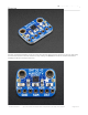
Power Pins:
Vin - this is the power pin. The chip can use 2.5-5VDC for power. To power the board, give it the same power as
the logic level of your microcontroller - e.g. for a 5V micro like Arduino, use 5V. For a 3.3V controller like a
Raspbery Pi, connect to 3.3V
GND - common ground for power and logic
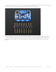
I2C Logic pins:
SCL - I2C clock pin, connect to your microcontrollers I2C clock line. This pin has a 10K pullup resistor to Vin
SDA - I2C data pin, connect to your microcontrollers I2C data line. This pin has a 10K pullup resistor to Vin
Other Pins:
ADR - This is the I2C address selection pin. This pin has a 10K pull down resistor to make the default I2C
address 0x44. You can tie this pin to Vin to make the address 0x45
RST - Hardware reset pint. Has a 10K pullup on it to make the chip active by default. Connect to ground to do a
hardware reset!
ALR - Alert/Interrupt output. You can set up the sensor to alert you when an event has occured. Check the
datasheet for how you can set up the alerts
© Adafruit Industries https://learn.adafruit.com/adafruit-sht31-d-temperature-and-humidity-sensor-breakout Page 6 of 20