
Datasheet


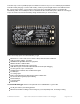


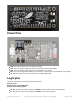


Power Pins
GND - this is the common ground for all power and logic
BAT - this is the positive voltage to/from the JST jack for the optional Lipoly battery
USB - this is the positive voltage to/from the micro USB jack if connected
EN - this is the 3.3V regulator's enable pin. It's pulled up, so connect to ground to disable the 3.3V regulator
3V - this is the output from the 3.3V regulator, it can supply 500mA peak
Logic pins
This is the general purpose I/O pin set for the microcontroller.
All logic is 3.3V
Nearly all pins can do PWM output
All pins can be interrupt inputs
#0 / RX - GPIO #0, also receive (input) pin for Serial1 (hardware UART), also can be analog input
#1 / TX - GPIO #1, also transmit (output) pin for Serial1, also can be analog input
© Adafruit Industries https://learn.adafruit.com/adafruit-feather-m0-adalogger Page 9 of 47