
Datasheet


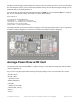


The above shows the Micro USB jack (left), Lipoly JST jack (top left), as well as the 3.3V regulator and changeover
diode (just to the right of the JST jack) and the Lipoly charging circuitry (to the right of the Reset button). There's
also a CHG LED, which will light up while the battery is charging. This LED might also flicker if the battery is not
connected.
Power supplies
You have a lot of power supply options here! We bring out the BAT pin, which is tied to the lipoly JST connector, as
well as USB which is the +5V from USB if connected. We also have the 3V pin which has the output from the 3.3V
regulator. We use a 500mA peak regulator. While you can get 500mA from it, you can't do it continuously from 5V as
it will overheat the regulator. It's fine for, say, powering an ESP8266 WiFi chip or XBee radio though, since the
current draw is 'spikey' & sporadic.
Measuring Battery
If you're running off of a battery, chances are you wanna know what the voltage is at! That way you can tell when
© Adafruit Industries https://learn.adafruit.com/adafruit-feather-m0-adalogger Page 22 of 47