
User Manual

Connections
These panels are normally designed for
chaining
(linking end-to-end into larger displays)…the output of one panel
connects to the input of the next, down the line.
With the limited RAM in an Arduino, chaining is seldom practical. Still, it’s necessary to distinguish the input and output
connections on the panel…it won’t respond if we’re connected to the wrong socket.
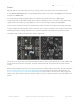
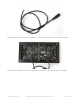
Flip the matrix over so you’re looking at the back, holding it with the two sockets situated at the left and right edges
(not top and bottom).
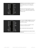
On some panels, if you’re lucky, the sockets are labeled INPUT and OUTPUT (sometimes IN and OUT or similar), so it’s
obvious which is the input socket.
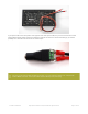
If INPUT is not labeled, look for one or more arrows pointing in the horizontal direction (ignore any vertical arrows,
whether up or down). The horizontal arrows show the direction data moves from INPUT to OUTPUT — then you know
which connector is which.
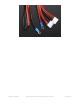
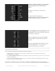
If no such labels are present, a last option is to examine the plastic shroud around the connector pins. The key (notch)
on the INPUT connector will face the outer edge of the panel (not the center).
The arrangement of pins on the INPUT connector varies with matrix size and the batch in which it was produced…
Although the panels support chaining, this is VERY impractical on Arduino-class boards and our library DOES
NOT SUPPORT it. A more powerful system like a Raspberry Pi may be a better choice for chained panels!
© Adafruit Industries https://learn.adafruit.com/32x16-32x32-rgb-led-matrix Page 9 of 44