
User Manual

Power
Although LEDs are very efficient light sources, get enough of them in one place and the current really adds up.
A
single
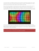
32x16 or 32x32 RGB matrix, running full tilt (all pixels set white), can require nearly
4 Amps
of current! Double
that figure for a 64x32 matrix.
On
average
though, displaying typical graphics and animation, these panels will use less…a 2A supply is
usually sufficient for a single 32x16 or 32x32 panel, or 4A for a 64x32 panel. There’s no harm in using a larger power
supply rated for more
Amps
(e.g. a 10A supply), but
never
use one with a higher
Voltage
(use 5V, period)!
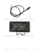
On these panels, the power connection is separate from the data connection. Let’s begin by connecting a 5V supply…
Our parts suppliers occasionally make revisions to designs. As a result, the connections have changed over time. We'll
walk through the different wiring combinations here…pick the explanation that matches the panel(s) you received.
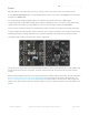
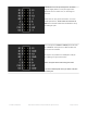
Two different types of power connectors have made an appearance:
On the left is a screw post power connector (with adjacent pads for soldering wires directly). On the right, a Molex-style
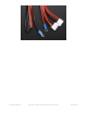
header. Some panels will have
two
headers…the power cable included with these panels has connectors for both
headers.
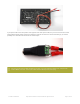
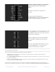
With the posts-and-pads connector, you can either screw down the spades from the power cable, or another approach
is to cut a 2.1mm jack from this extension cord (http://adafru.it/327) and solder it to the pads on the panel back. This
way you can plug the 5V from a wall adapter (http://adafru.it/276) right in (the one we have in the shop is suggested).
Simply cut the other half of the cable off, and strip the wiring so you can solder the red wire to +5 and the black wire to
ground.
© Adafruit Industries https://learn.adafruit.com/32x16-32x32-rgb-led-matrix Page 5 of 44