
User Manual

How the Matrix Works
There's zero documention out there on how these matrices work, and no public datasheets or spec sheets so we are
going to try to document how they work.
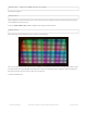
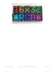
First thing to notice is that there are 512 RGB LEDs in a 16x32 matrix. Like pretty much every matrix out there, you can't
drive all 512 at once. One reason is that would require a lot of current, another reason is that it would be really
expensive to have so many pins. Instead, the matrix is divided into 8 interleaved sections/strips. The first section is the
1st 'line' and the 9th 'line' (32 x 2 RGB LEDs = 64 RGB LEDs), the second is the 2nd and 10th line, etc until the last
section which is the 7th and 16th line. You might be asking, why are the lines paired this way? wouldnt it be nicer to
have the first section be the 1st and 2nd line, then 3rd and 4th, until the 15th and 16th? The reason they do it this way is
so that the lines are interleaved and look better when refreshed, otherwise we'd see the stripes more clearly.
So, on the PCB is 12 LED driver chips. These are like 74HC595s but they have 16 outputs and they are constant
current. 16 outputs * 12 chips = 192 LEDs that can be controlled at once, and 64 * 3 (R G and B) = 192. So now the
design comes together: You have 192 outputs that can control one line at a time, with each of 192 R, G and B LEDs
either on or off. The controller (say an FPGA or microcontroller) selects which section to currently draw (using A, B, and
C address pins - 3 bits can have 8 values). Once the address is set, the controller clocks out 192 bits of data (24 bytes)
and latches it. Then it increments the address and clocks out another 192 bits, etc until it gets to address #7, then it
sets the address back to #0
The only downside of this technique is that despite being very simple and fast, it has no PWM control built in! The
controller can only set the LEDs on or off. So what do you do when you want full color? You actually need to draw the
entire matrix over and over again at very high speeds to PWM the matrix manually. For that reason, you need to have a
very fast controller (50 MHz is a minimum) if you want to do a lot of colors and motion video and have it look good.
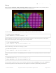
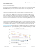
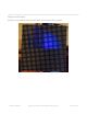
How quickly can we feed data to the matrix? Forum users Andrew Silverman and Ryan Brown have been posting their
progress (https://adafru.it/aO2) driving the 16x32 matrix with an FPGA, and the limit appears to be somewhere between
40 and 50 MHz. Ryan writes: “I haven't validated 100% pixel correctness, but 50 MHz seems to work for me […] 67MHz
definitely did not work.” He also provided this graph showing current draw relative to clock frequency:
© Adafruit Industries https://learn.adafruit.com/32x16-32x32-rgb-led-matrix Page 38 of 44