
User Manual
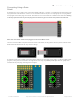
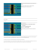

Wires are then soldered from the header to specific Arduino pins on the proto shield. Try to keep wire lengths
reasonably short to avoid signal interference.
Using color-coded wires helps a
lot!
If you don’t have colored wires, that’s okay, just pay close attention where
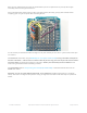
everything goes. Our goal is a proto shield something like this:
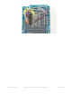
It’s not necessary to install all the buttons and lights on the proto shield if you don’t want — just the basic header pins
are sufficient.
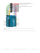
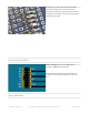
For Arduino Uno and similar, using an Adafruit proto shield (https://adafru.it/eUM): if using a shrouded socket (like on
the back of the matrix — with the notch so a ribbon cable only fits one way) you’ll need to place this near the “Reset”
end of the shield. The plastic shroud obscures a lot of pins. Others’ proto shields may be laid out different…look
around for a good location before committing to solder.
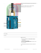
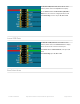
For Arduino Mega with our corresponding proto shield (http://adafru.it/192): a shrouded socket fits best near the
middle of the shield.
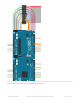
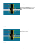
Otherwise, you can use a plain 2x8-pin male header, or two 1x8 sections installed side-by-side (as in the photo
above). Since there’s no alignment key with this setup, you might want to indicate it with some tape or a permanent
marker.
© Adafruit Industries https://learn.adafruit.com/32x16-32x32-rgb-led-matrix Page 26 of 44