
User Manual
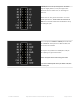

“Variant B” for 32x32 and 64x32 panels. The wiring is
identical
to Variant A above,
only the labels
are
different.
Ground pins aren’t labeled, but still need to be
connected.
LAT (latch) is labeled STB (strobe) here.
R1/G1/B1/R2/G2/B2 are changed to R0/G0/B0/R1/G1/B1…
but again, no functional difference, it’s just ink.
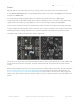
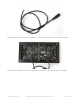
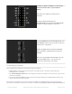
Our earliest 32x32 panels had a two-socket design, let’s
call it “Variant C.” All the same pin functions are present
but the layout is very different.
R/G/B on the upper socket correspond to R1/G1/B1 in
Variant A. R/G/B on the lower socket correspond to
R2/G2/B2.
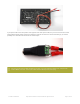
All the other signals (A/B/C/D/CLK/LAT/OE) need to be
connected to both sockets — e.g. one pin on the
Arduino drives both CLK pins, and so forth.
Connecting to Arduino
There are two or three methods for connecting a matrix to an Arduino:
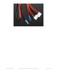
1. Jumper wires inserted between Arduino headers and a ribbon cable — this works well for testing and
prototyping, but is not durable.
2. The Adafruit RGB Matrix Shield makes connecting these panels to an Arduino as easy as can be, and is best for
permanent installations.
3. One could build a
proto shield
to replicate the pinout of option #2. But given the Matrix Shield’s low cost, this
might not be worth the effort nowadays.
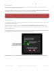
These panels are normally run by very fast processors or FPGAs, not a 16 MHz Arduino. To achieve reasonable
performance in this limited environment, our software is optimized by tying specific signals to specific Arduino pins. A
© Adafruit Industries https://learn.adafruit.com/32x16-32x32-rgb-led-matrix Page 11 of 44