
Datasheet


send and receive commands and data. These pins are auto-baud so whatever baud rate you send "AT" after
reset or boot is the baud rate is used. RX is into the module, TX is out of the module.
RTS - this is the hardware flow control pin. If you turn on flow control on the SIM808 you can use this pin to stop
and start data transfer
from
the SIM808 to your microcontroller
RI - this is the Ring Indicator. It is basically the 'interrupt' out pin from the module. It is by default high and will
pulse low for 120ms when a call is received. It can also be configured to pulse when an SMS is received.
SPK+ and - : This is for connecting an external 32 ohm speaker. This is shared with the headphone jack. The two
pins are differential so they don't have output DC blocking capacitors. You cannot connect this to a stereo,
powered speakers or other non-differential amplifier without adding a 100uF+ blocking cap in series to the + pin
and then not using the - pin. Instead, your amp should use GND for the - reference
MIC + and -: this is for connecting an external electret microphone, it will bias the mic with 2V. Most electrets will
work just fine. No extra circuitry is required for the mic such as a biaser or amplifier, just wire it up directly!
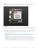
LEDs
PWR - Blue! Lit when the module is booted and running
NET - Red! You can use this for checking the current state without sending an AT command:
64ms on, 800ms off - the module is running but hasn't made connection to the cellular network yet
64ms on, 3 seconds off - the module has made contact with the cellular network and can send/receive voice
and SMS
64ms on, 300ms off - the GPRS data connection you requested is active
By watching the blinks you can get a visual feedback on whats going on.
Charging - Orange! This is next to the microUSB jack. Indicates the onboard lipo charger is charging
Done - Green! This is next to the JST jack. Indicates that the battery charging is done and the battery is full
Other Breakout Pins
We scattered a few other breakouts around the board.
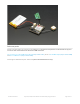
Buzzer and PWM (Top right) - These are tied to the PWM output of the module! The PWM capability is quite nice,
it can set any frequency and duty cycle. The PWM pin is directly output from the module and is 0-2.8Vpp. The
Buzzer output has a NPN drive transistor so it can run a small vibration motor. Bz+ is the VBat voltage, Bz- is
toggled on and off to ground.
ADC (left middle) - the SIM800 has an ADC that can read 0-2.8VDC from this pin, referenced to ground. It also
has an internal battery ADC so you can use this for a sensor or something. You can query the voltage from the
UART. 2.8V max, people!
2.8V test point - We have a test point for the 2.8V internal regulator, its off to the right.
© Adafruit Industries https://learn.adafruit.com/adafruit-fona-808-cellular-plus-gps-breakout Page 15 of 57