
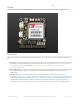
Datasheet
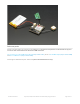


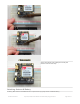


Bottom Breakouts
The most important pins are broken out at the bottom of the board. Not all of these are required, but they are all hella
useful
These are in rough order of most important (not in linear order like we usually do)
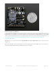
These pins are all 3-5V input safe and if they are an output, the logic level is whatever Vio is set to.
Vio - THIS IS THE MOST IMPORTANT PIN! This is the pin that you MUST drive with an external voltage from 3V-
5V to set the logic level converter. The converter also buffers the indicator LEDs so NOTHING will appear to
work unless this pin is powered! You should set the voltage to whatever voltage your microcontroller uses for
logic. A 5V micro (like Arduino) should have it be 5V, a 3V logic micro should set it to 3V.
Key - This is also a super important pin (but not as important as Vio). This is the power on/off indicator. Its also
tied to the button in the top left. Tie this pin to ground for 2 seconds to turn the module on or off. It's not a level
signal so it isn't like "low is off, high is on" - instead you must pulse it for 2 seconds to turn off/on. The module
comes by default off. Tie this permanently to ground if you never want your micro to turn off the FONA for power
saving
5V - this is the USB 5V from the microUSB connector when its in and powered. Good if you need to know when
the microUSB is plugged in and/or want to recharge the battery from an external plug.
PS - this is the Power Status pin. It is low when the module is off and high when the module has power. If you're
using the Key button or pin, you can monitor this pad to see when the module's booted up. This is tied to the Pwr
LED too.
NS - this is the Network Status pin. It pulses to signal the current status of the module. This is also tied to the Net
LED so for more detail see the LEDs section below.
Reset - this is module hard reset pin. By default it has a high pull-up (module not in reset). If you absolutely got
the module in a bad space, toggle this pin low for 100ms to perform a hard reset.
RX & TX - OK now that I made you read all that you can actually use the UART pins. The module uses UART to
© Adafruit Industries https://learn.adafruit.com/adafruit-fona-808-cellular-plus-gps-breakout Page 14 of 57