
Installation manual

Page 36
INPUT
#
INPUT LABEL
AUDIO
INPUT
ALTERNATE
AUDIO INPUT
COMPOSITE
VIDEO
INPUT
S-VIDEO
INPUT
COMPONENT
VIDEO
INPUT
1 DVD PLAYER DIGITAL 1 - 1 1 1
2 DSS OPTICAL 2 DIGITAL 2 2 2 2
3 DVR/PVR ANALOG 3 OPTICAL 3 3 3 -
4 VCR ANALOG 4 - 4 4 -
5 CABLE/TV ANALOG 5 OPTICAL 4 5 - -
6 CD PLAYER ANALOG 6 OPTICAL 1 - - -
7 TUNER ANALOG 7 - - - -
8 AUXILIARY ANALOG 8 - 8 - -
9 DVD AUDIO MULTI-PIN - 1 1 1
1 0 MULTI-ROOM ANALOG 2 - - - -
1 1 CAMCORDER ANALOG 1 - 7 - -
1 2 VIDEO GAME DIGITAL 3 OPTICAL 1 6 - 3
1 3 COMPUTER DIGITAL 4 OPTICAL 1 6 - -
1 4 LASERDISC OPTICAL 1 - 8 - -
1 5 LASER AC3 DIGITAL 2 - 8 - -
1 6 PHONOGRPH ANALOG 1 - - - -
1 7 DSS RECORD ANALOG 2 - 2 2 2
1 8 DVR RECORD ANALOG 3 - 3 3 -
1 9 TV RECORD ANALOG 5 - 5 - -
2 0 CD RECORD ANALOG 6 - - - -
20 Turn the Mode knob counterclockwise until the R is replaced with letter O and then press the
Mode Knob.
21 With the display now reading <DSS RECOY 8>, turn the Mode knob clockwise one click until
the Y is flashing and press the Mode knob.
22 Turn the Mode knob counterclockwise until the Y is replaced with letter D and then press the
Mode Knob.
23 With the display now reading <DSS RECOR 8>, turn the Mode knob clockwise one click until
the blank space is flashing and press the Mode knob.
24 Turn the Mode knob counterclockwise until the blank space is replaced with letter D and then
press the Mode Knob.
25 With the display now reading <DSS RECORD 8>, turn the Mode knob clockwise until the
display read’s BACK TO LABL and press the Mode knob.
26 To continue with other setup options, turn the mode knob clockwise until the display reads
BACK TO MAIN. To exit the setup mode entirely, turn the Volume knob.
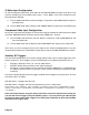
Audio Input Configuration
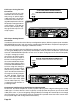
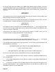
The Cinema Rhapsody Mach II is extraordinarily flexible in that any A/V jack on the back of the unit
can be assigned to any input label. Also, a specific A/V jack can be assigned to multiple input labels.
While the Out of the Box input configuration of the Cinema Rhapsody Mach II has the jacks preas-
signed as noted in the previous sections, you may wish to alter some of these conditions when cus-
tomizing your system. Use the Out of the Box input configuration chart below as a guide to determin-
ing what jacks are already assigned in the Out of the Box setup.
Taking the example in this section with the eight input labels, the first seven input labels follow the Out
of the Box setup. The eight input label, previously AUXILIARY now labeled DSS RECORD, will re-
quire alteration.