
User`s manual


AD-net Technology. CO LTD
- 6 - www.ad-net.com.tw
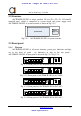
2.3.2 LED’s
The definition is shown in Table 2.3.2-1:
Table 2.3.2-1 the indicators definition of AN-TDM-IP-1E1/2E1-A
Identification Color
Quantity
Definition
Remark
SYS Green
1
System working state
instructions
Blink: Normal
On: System is on
configuration or work
abnormally
Off: System does not
work or abnormally work
PWR FAIL Red 1
The power failure alarm
instructions
On: Power Off / Failure
Off: Normal
L/A Green 1
0ptical Ethernet interface
state instructions
On: Connected with
remote Ethernet optical
interface
Off: Not connected with
Ethernet optical interface
Optical
Ethernet
interface
indicators
OLOS Red 1
Optical Ethernet
interface receiving
instructions
On: No receiving
Off: Receiving normally
(Ethernet
electrical
port LINK)
Green 4
Ethernet electrical
interface instructions
On: Link normally
Blink: Data
transmitting/receiving
Off: Link abnormally
One link
indicator
on the left
of each
Ethernet
electrical
interface
(Ethernet
electrical
port FDX)
Yellow 4
Ethernet electrical
interface rate
instructions:
On :rate is HULL
Off :rate is HALF
One FDX
indicator
on the
right of
Ethernet
electrical
interface
Manuel de l'usager du Mux IP vers 2xE1
www.hypercable.fr