
Troubleshooting guide


TROUBLESHOOTING GUIDE
MILLPWR
®
Operation Manual
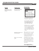
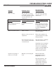
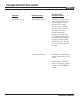
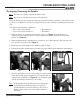
1. When the head is re-positioned to mill certain angles (see Figure 1) torque the four (4)
coupling nuts that secure the Z-axis casting to the head to 50 ft/lbs while the head is in that
position (see Figure 2).
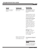
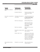
2. When the milling head is repositioned to “0” degrees, use a dial indicator to fine-tune the accu-
racy of the head’s position (see Figure 3).
3. Ensure the knee lock clamps on the machine saddle are tight.
4. Follow the machine manufacturer’s procedure for proper milling head calibration and alignment.
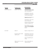
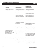
5. Once the dial indicator shows a “0” reading in several locations
of the table and the head is trammed in, re-torque the four (4)
coupling nuts to 50 ft/lbs (see Figure 4). As you tighten, make
sure the dial indicator maintains its “0” reading.
9-15
Re-aligning (Tramming) the Spindle
You will need the following components:
• Box or open-ended wrench
• Crow’s foot torque wrench 7/8”
When the head has been re-angled the following procedure should be performed so the original accura-
cy can be re-established. Do not loosen casting bolts or hex nuts; loosen the tramming hex stand-offs
only.
• Dial indicator
• Dial holder
Note: This does not require re-aligning the quill casting.
Fig. 1
Fig. 2
Fig. 3
Fig. 4
Note: If the 50 ft/lbs torque specification is not applied, the
engage/disengage mechanism may not engage the
Z-axis ballscrew nut correctly. This may also create a
binding and/or undue wear to the spindle within the
mill head.
Note: The Z-axis is still fully functional in a tilted position.