MILLPWR Setup Access Code An access code must be entered before the installation setup parameters can be accessed or changed. IMPORTANT The access code is 8891. Refer to Section 7, Setup. IMPORTANT Supervisors may wish to remove this page from the MILLPWR Operation Manual after initially setting up the installation setup parameters. Keep it in a safe place for future use.
TABLE OF CONTENTS MILLPWR ® Introduction . . . . . . . . . . . . . . . . . . . . . . . . . . . . . . . . . . . . . . . . . . . . . . . . . .1-1 System Overview . . . . . . . . . . . . . . . . . . . . . . . . . . . . . . . . . . . . . . . . . . .1-1 Operator Console Overview . . . . . . . . . . . . . . . . . . . . . . . . . . . . . . . .1-2 Keypad Layout . . . . . . . . . . . . . . . . . . . . . . . . . . . . . . . . . . . . . . . . .1-3 Screen Layout . . . . . . . . . . . . . . . . . . . . . . . . . . . .
TABLE OF CONTENTS MILLPWR ® Programming . . . . . . . . . . . . . . . . . . . . . . . . . . . . . . . . . . . . . . . . . . . . . . . . .3-1 Programming Considerations . . . . . . . . . . . . . . . . . . . . . . . . . . . . . . . . . .3-1 “From” and “To” Points . . . . . . . . . . . . . . . . . . . . . . . . . . . . . . . . . . .3-1 Depth of Cut . . . . . . . . . . . . . . . . . . . . . . . . . . . . . . . . . . . . . . . . . . .3-1 Pass . . . . . . . . . . . . . . . . . . . . . . . . . . . . . . . . . . .
TABLE OF CONTENTS MILLPWR ® Loading a G-code file . . . . . . . . . . . . . . . . . . . . . . . . . . . . . . . . . . . . .3-29 Running a G-code Program . . . . . . . . . . . . . . . . . . . . . . . . . . . . . . . . .3-31 MILLPWR - G-code Conventions . . . . . . . . . . . . . . . . . . . . . . . . . . . . .3-33 Merging Programs . . . . . . . . . . . . . . . . . . . . . . . . . . . . . . . . . . . . . . .3-37 Backing Up a Program . . . . . . . . . . . . . . . . . . . . . . . . . . . . . . . . . . . .
TABLE OF CONTENTS MILLPWR ® Circular Milling Functions . . . . . . . . . . . . . . . . . . . . . . . . . . . . . . . . . . . .5-22 Pocket . . . . . . . . . . . . . . . . . . . . . . . . . . . . . . . . . . . . . . . . . . . . . . . . .5-22 Frame . . . . . . . . . . . . . . . . . . . . . . . . . . . . . . . . . . . . . . . . . . . . . . . . .5-24 Ring . . . . . . . . . . . . . . . . . . . . . . . . . . . . . . . . . . . . . . . . . . . . . . . . . .5-26 Helix . . . . . . . . . . . . . . . . . . . . . . . .
TABLE OF CONTENTS MILLPWR ® Working with the Geometry Calculator . . . . . . . . . . . . . . . . . . . . . . .6-4 GeoCalc™ Quick Reference Table . . . . . . . . . . . . . . . . . . . . . . . . . . . .6-5 Using GeoCalc . . . . . . . . . . . . . . . . . . . . . . . . . . . . . . . . . . . . . . . . . .6-6 Calculator Functions . . . . . . . . . . . . . . . . . . . . . . . . . . . . . . . . . . . . . .6-7 Saving Results Calculated in GeoCalc . . . . . . . . . . . . . . . . . . . . . .
TABLE OF CONTENTS MILLPWR ® Min % . . . . . . . . . . . . . . . . . . . . . . . . . . . . . . . . . . . . . . . . . . . . . .7-16 Dry Run Speed . . . . . . . . . . . . . . . . . . . . . . . . . . . . . . . . . . . . . . .7-16 Default Feed Rate . . . . . . . . . . . . . . . . . . . . . . . . . . . . . . . . . . . . .7-16 Unit/(Min) . . . . . . . . . . . . . . . . . . . . . . . . . . . . . . . . . . . . . . . . . . .7-16 Full Cut Feed Rate % . . . . . . . . . . . . . . . . . . . . . . . . . . . . . . . . . .
TABLE OF CONTENTS MILLPWR ® Connecting MILLPWR to Your PC . . . . . . . . . . . . . . . . . . . . . . . . . . . . . . . 8-2 Installing the Remote Storage Program onto Your PC . . . . . . . . . . . . . 8-3 For Windows 95 and 98 . . . . . . . . . . . . . . . . . . . . . . . . . . . . . . . . . . .8-3 For MS DOS . . . . . . . . . . . . . . . . . . . . . . . . . . . . . . . . . . . . . . . . . . . 8-3 Setting Up Your COM Port and BAUD Rates . . . . . . . . . . . . . . . . . . . . . .
This symbol alerts you to important information concerning the operation of your MILLPWR system.
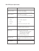
MILLPWR System Specifications Characteristic Specification Operating conditions 0° to 40° C (32° to 104° F) 25% to 85% relative humidity (non-condensing) Storage conditions -20° to 60° C (-4° to 140° F) 25% to 95% relative humidty (non-condensing) Input requirements: Voltage 115V~ (±20%), single phase Frequency 47 - 63 Hz Current 8.5A rms nom.
INTRODUCTION MILLPWR ® INTRODUCTION System Overview Operator Console Motor Drive Assemblies ACU-RITE™ Scales Licensed under U. S. Patent No.
INTRODUCTION MILLPWR ® Front View of Operator Console Rear View of Operator Console 1-2 Operation Manual
INTRODUCTION MILLPWR ® Keypad Layout Main Function Keys Cursor and Motion Control Switch from absolute to incremental (or vice versa) in the DRO display and milling function numeric fields. Manipulate your part graphic. GO Start your program. STOP Press this key once to pause your program, twice to exit. FEED+ FEED- Increase or decrease your feed rate. Display the digital readout. Display the program screen. Exit from a milling function.
INTRODUCTION MILLPWR ® Screen Layout The MILLPWR display screen is divided into four sections. Status bar - displays the servo motor status (ON/OFF), feed rate, current tool, scale, job clock, and the current display setting (inches or millimeters). Information area - displays information about the job being performed. • Readout (DRO) - used as a digital readout, the display will show the current position for each axis.
INTRODUCTION MILLPWR ® Table Stop Button The large red button located in the lower left corner on the front of your MILLPWR operator console is the TABLE STOP. In the event of a malfunction or programming error, press the TABLE STOP button to turn off the servo motors. This will immediately stop all positioning for each axis. WARNING! Pressing the TABLE STOP button will NOT stop the rotation of the cutting tool unless your machine has been configured to do so.
INTRODUCTION MILLPWR ® Conventions Axis Conventions Count Direction When programming a part using MILLPWR, table movement and tool movement are determined by the use of positive or negative numbers. MILLPWR has been factory set with the following positive and negative count directions for the X, Y and Z-axes: X-axis: The table will move to the left and the tool will move to the right for a positive count direction.
INTRODUCTION MILLPWR ® Cartesian Coordinates A cartesian coordinate is a position that can be measured from the X- and Y-axes. Polar Coordinates A polar coordinate is a position that is defined by an angle and a radius.
INTRODUCTION MILLPWR ® Absolute and Incremental Dimensions Dimensions that you enter from a print are either absolute or incremental. Absolute dimensions are measured from datum (also known as workpiece zero). Incremental dimensions are measured from one point to another. Holes A and B are dimensioned using absolute values. Hole C is dimensioned incrementally from Hole A. When entering these dimensions, we would say: Hole A: 002 Position/Drill X 2.0000 ABS Y 1.5000 ABS Hole B: 003 Position/Drill X 4.
INTRODUCTION MILLPWR ® Z-axis Conventions Z-axis Retract The Z-axis retract is the position the quill returns to between program steps. By setting a retract position, you can ensure that the tool you are using does not make contact with your workpiece when the quill moves from one position to the next. It’s a good idea to establish a retract position for the Z-axis each time you power up your system; otherwise, MILLPWR will use the quill’s upper travel limit as the Z-axis retract position.
INTRODUCTION MILLPWR ® Disengaging the Z-axis Drive System (Rotary Encoder) provides you with the flexibility to switch between twoaxes and three-axes operation. MILLPWR To disengage the Z-axis drive system from your MILLPWR system: • Leave the “Begin” field blank when you program a step or a one-time milling function. • Raise the quill, then loosen the quick release knob located on the front of the Z-axis drive system.
INTRODUCTION MILLPWR ® Disengaging the Z-axis Drive System (Linear Encoder Option) MILLPWR provides you with the flexibility to switch between two-axes and three-axes operation. To disengage the Z-axis drive system from your MILLPWR system: • Leave the “Begin” field blank when you program a step or a one-time milling function. • Raise the quill, then loosen the quick release knob located on the front of the Z-axis drive system.
INTRODUCTION MILLPWR ® Setting Z-axis Datum when Changing Tools Whenever you encounter a SET TOOL step, MILLPWR will display the DRO screen and let you know which tool to load. If no tool diameter was programmed in the “Tool Step,” you will be prompted to provide one. • Use the MOVE TABLE softkey and arrow keys to move the tool away from your workpiece. • Press the move table softkey again to turn off the motors. • Insert the required tool into the spindle.
INTRODUCTION MILLPWR ® Saving, Backing Up, and Creating Directories for Programs When you create programs with MILLPWR, you can save them in any of three places—within MILLPWR's internal memory, on a 31/2" floppy disk, or on your PC using Remote Storage. Saving your work means it will not be lost if MILLPWR is powered down or if there is a power interruption. is also equipped with a back up feature that enables you to make duplicate copies of your saved programs to floppy disc or Remote Storage.
DRO MILLPWR ® DRO Start Up Power Up Press the power switch (located on the rear of the operator console) to “I.” The Power Indicator (located in the upper left corner of the operator console) will light up green. Once MILLPWR has been powered up, the following screen will appear: Screen Saver Anytime your system is inactive for approximately 90 minutes, the LCD display will shut off, and a blank screen will appear.
DRO MILLPWR ® Finding Home (Rotary Encoder) If you don't find home before moving the table, you will risk exceeding the table's travel limits and damaging the milling machine, MILLPWR or both. You must find home before you run a program. To find home immediately after startup, locate the Z-axis at the top of the fixed mark then press the FIND HOME softkey. Otherwise, press the DATUM softkey, then the FIND HOME softkey.
DRO MILLPWR ® Finding Home (Linear Encoder Option) If you don't find home before moving the table, you will risk exceeding the table's travel limits and damaging the milling machine, MILLPWR or both. You must find home before you run a program. To find home immediately after startup, press the FIND HOME softkey. Otherwise, press the DATUM softkey, then the FIND HOME softkey. The table will automatically move a few inches along the Z-, Y- and then X-axes to find home.
DRO MILLPWR ® DRO Functions The digital readout (DRO) display shows you the current tool position. While operating in the DRO mode, you can use several functions, such as skew and datum, to set up your job. You can also use this as a standard DRO when you use your machine manually. Move Table The move table feature lets you move the table rapidly (or at an established feed rate) using the arrow keys. 2-4 • Press the MOVE TABLE softkey to turn the servo motors on. Press it again to turn them off.
DRO MILLPWR ® Zeroing an Axis Pressing the ZERO X, ZERO Y or ZERO Z softkeys will zero the incremental position for those axes. You need to set datum to establish the point from which all absolute dimensions are based. Inch/millimeter You can display inch or millimeter positions. Press the MM key to switch from one to the other. Teach Position Whenever X, Y or Z coordinates are being entered, the TEACH POSITION softkey will appear, enabling you to “teach” MILLPWR the coordinate(s) you want to use.
DRO MILLPWR ® Using an Electronic Edge Finder An ACU-RITE® Electronic Edge Finder enables you to “teach” positions, find the center point of a circle, skew a part or locate datum (also known as workpiece zero) by simply “touching off” on the part. The greatest advantage of an electronic edge finder is that it instantly senses when you’ve made contact with the point —even when you over-travel. lets you define the “Diameter” and “Unit” of measure (either inches or millimeters) for an electronic edge finder.
DRO MILLPWR ® Skewing a Part With MILLPWR, you can save time setting up a job by skewing your part. The skew function automatically compensates for the offset angle of your part—so if your part is not perfectly parallel with either the X- or Y-axis, you won’t have to spend time indicating it in. To skew a part, simply “touch off” on two or more points along one axis (either X or Y).
DRO MILLPWR ® To skew a part or vise: Using an electronic edge finder • Press the SKEW softkey. • Touch off on two or more points along any single straight edge of your part. You’ll notice the “Points” and “Angle” change as you enter points. MILLPWR will calculate the angle to the closest axis line and compensate for the offset of the workpiece. • Press the USE key to accept all of the points and return to the DRO screen.
DRO MILLPWR ® Establishing Datum Datum, also known as workpiece zero or absolute zero, is a point of reference that MILLPWR bases all of your part's coordinates from. Datum will need to be established for every job. Datum's location may be indicated on your print; if it's not, establish a datum that allows you to enter most of the part's dimensions directly, with the least amount of calculations.
DRO MILLPWR ® • Position the tool so that it is near, but not touching, the left side of the part. • Lower the tip of the tool so that it falls below the top surface of the part. • Slowly move the table along the X-axis, spinning the tool by hand as you go. Pay close attention as the tool approaches the part—you'll feel a subtle bump when they come into contact. Stop the table at the moment the tool touches the part.
DRO MILLPWR ® Setting datum for the Z-axis: • Position the tool so that its tip touches the top surface of the part. • Using the keypad, enter "0" into the "Z" field (or press the Z = 0 softkey). • Press the ENTER key. • Highlight the “Z Retract” field. • Either: Enter the Z-axis retract position (the position that you want the quill to return to between steps—it must be located above the top surface of the part); OR Raise the quill to the desired retract position, then press the TEACH softkey.
DRO MILLPWR ® Hard Key Milling Functions Most of the hard key milling functions can be used individually as one time milling routines. That means you can use these keys without creating a program. The only hard key milling function you can’t use as a one-time milling function is BLEND. The blend function inserts a connecting radius between two features (steps) in a program. Hard key milling functions are ideal for jobs that only require one operation.
DRO MILLPWR ® To change the hole pattern size, depth, location, number of holes, etc., press the HOLES key again. Now press the appropriate softkey, enter the new information and then press the GO key. This also applies to rectangles, circles, lines and arcs. The rectangle and circle milling functions require you to establish a tool offset. Lines and arcs only require a tool offset if the tool follows the left or right edge. It’s a good idea to setup the tool before using either of these function keys.
PROGRAMMING MILLPWR ® PROGRAMMING Programming Considerations "From" and "To" Points Lines and arcs are defined by their “From” point (the point where they begin) and “To” point (the point where they end). Depth of Cut When you’re programming the depth of cut, you’ll be prompted to provide the “Begin” and “End” locations for the Z-axis. The location that you enter into the “Begin” field tells MILLPWR where you want the quill to begin cutting at the programmed feed rate.
PROGRAMMING MILLPWR ® Tool Offset With MILLPWR, you never have to calculate the actual tool path. By using left and right offsets, you can program the dimensions of the part as identified on your print. When you program a line, arc, frame, etc., use the “Tool Offset” field to tell MILLPWR which side of the line you want the tool to be on. To determine which offset to use, picture yourself following the tool as it is moving. If the tool needs to be on the left side of the line, use a "left" offset.
PROGRAMMING MILLPWR ® Absolute vs. Incremental Dimensions allows you to enter both absolute and incremental dimensions. A dimension measured from the point you defined as datum is an absolute dimension. A dimension measured from any other point is an incremental dimension. MILLPWR In the examples below, the print on the left shows datum located at the center of Hole F—all dimensions are absolute. The print on the right shows datum located in the lower left corner—point A.
PROGRAMMING MILLPWR ® If one step follows another, MILLPWR assumes that you want them to be connected. It automatically fills in the “From” point, “Depth,” and “Tool Offset.” All you have to do is fill in the “To” point and press USE. Note: MILLPWR will allow you to program different feed rates within each step of a continuous contour. Single lines indicate an open-ended continuous tool path. Double lines indicate a closed continuous tool path.
PROGRAMMING MILLPWR ® Creating a Program • Press the PGM key, and the following program screen will appear. Programs are created by developing a list of milling steps to be performed. As you add to your list, each step will immediately be drawn on the screen so that you can see a graphic display of your part in progress. • To enter a milling step, press the appropriate hard key milling function (such as Tool).
PROGRAMMING MILLPWR ® • After entering all the data for a step, press the USE key to add the step to your program. This immediately updates the part graphic and positions the cursor for the next step. If you decide not to finish a milling function that you have begun, simply press the CANCEL key. • To edit a step, use the arrow keys to highlight the step you want to change and press USE or ENTER.
PROGRAMMING MILLPWR ® The View Key If you need to see your part-graphic in more detail, press the VIEW key. This enables you to access the following softkeys: The FOLLOW TOOL, SHOW TOOL PATH and ZOOM functions may be used simultaneously. Press the VIEW key (or the CANCEL key) at any time to return to the PGM screen. FOLLOW TOOL Press both the FOLLOW TOOL and ZOOM IN softkeys to see a close-up of the tool’s path. MILLPWR will automatically adjust the part graphic so that the tool is always in view.
PROGRAMMING MILLPWR ® Running a Program There are a few things you'll need to do before running a program, such as skewing the part and establishing datum. Skewing a Part Note: It is important to skew a part prior to establishing datum for accuracy. With MILLPWR, you can save time setting up a job by skewing your part.
PROGRAMMING MILLPWR ® Using an electronic edge finder: • From the DRO screen, press the SKEW softkey. • Touch off on two or more points along any single straight edge of your part. You’ll notice that the “Points” and “Angle” change as you enter points. • Press USE to accept all of the points and return to the DRO screen. Press CANCEL to return to the DRO screen without accepting any points or affecting your previous skew angle.
PROGRAMMING MILLPWR ® Establishing Datum Datum, also known as workpiece zero or absolute zero, is a point of reference that MILLPWR bases all of your part's coordinates from. You will need to establish datum for every job. Datum's location may be indicated on your print; if it's not, then establish a datum that allows you to enter most of your part's dimensions directly, with the least amount of calculations.
PROGRAMMING MILLPWR ® • Position the tool so that it is near, but not touching, the left side of your part. • Lower the tip of the tool so that it falls below the top surface of the part. • Move the table along the X-axis, slowly spinning the tool by hand as you go. Pay close attention as the tool approaches the part—you'll feel a subtle bump when they come into contact. Stop the table at the moment the tool touches the part.
PROGRAMMING MILLPWR ® Finally, we'll set datum for the Z-axis: • Position the tool so that its tip touches the top surface of your part. • Using the keypad, enter "0" into the "Z:" field (or press the Z = 0 softkey). • Press the ENTER key. • Highlight the “Z Retract” field.
PROGRAMMING MILLPWR ® Testing Your MILLPWR Program Whenever you are about to run a program, check that the handles are recessed. Before you machine a part, it is always a good idea for you to test your program for things like the correct tool path, count direction, feed rate, and sequence of operations. MILLPWR provides several run-time options to assist you.
PROGRAMMING MILLPWR ® MANUAL POSITIONING Use this option if you want to position the table using the handles. MILLPWR will operate just like a programmable readout—each target position will be preset into the readout, and you will be prompted to position the table manually. This feature is especially useful when you’re navigating around islands. Press the GO key to begin.
PROGRAMMING MILLPWR ® Machining Your Part Whenever you are about to run a program, check that the handles are recessed. Before you run a program step, check the “Status” bar (located along the top of the MILLPWR screen) to ensure that the tool identified by MILLPWR matches the tool in the spindle. If there’s no tool identified, or if it’s incorrect, you’ll need to start with a “Set Tool” step that accurately identifies the tool you’re using (refer to Set Tool).
PROGRAMMING MILLPWR ® Feed+ and FeedThe FEED+ and FEED- keys will change your feed rate by a certain percentage with each key press. The feed rate percentage will be displayed in the status bar at the top of the screen. A feed rate percentage of 100% means that actual feed rates will run at 100% of the programmed feed rates. If the feed rate percentage is 50%, actual feed rates will run at half of the programmed feed rates.
PROGRAMMING MILLPWR ® Program Functions Accessing Load, Save, Delete, Merge, Backup and Directory Options offers several versatile features for loading, saving, deleting, merging and backing up your programs. You can also easily organize your programs by creating directories. MILLPWR To access these features, from the PGM screen, press the PROGRAM FUNCTIONS softkey.
PROGRAMMING MILLPWR ® Directories One of the best ways to keep your programs organized is to save them in directories. Directories are like file folders—they should be clearly labeled and contain closely related programs. They may be used to group programs by job, operator, date, customer, or any other method you prefer. • Press the PROGRAM FUNCTIONS softkey, then press the DIRECTORY softkey. Now you can open an existing directory, create a new directory, or delete a directory that you no longer need.
PROGRAMMING MILLPWR ® Creating a Subdirectory The best approach to take when creating a subdirectory is to decide first where to place it. You can place it on the "MILLPWR directory," on a floppy disk ("A:") directory or on your PC ("REMTSTOR") directory, or you can place it within subdirectories that you have already created. In the example below, we’ve created four subdirectories in the MILLPWR folder. Three of the subdirectories are named for our top customers: COMPANY1, COMPANY2 and COMPANY3.
PROGRAMMING MILLPWR ® To create directories for your programs: • Press the PGM key, the PROGRAM FUNCTIONS softkey and then the DIRECTORY softkey. Now press the SELECT DIRECTORY softkey, and a directory list will appear. • Highlight the directory where you want to store your new subdirectory. Select MILLPWR's internal memory: "MILLPWR" and any subdirectories should appear under the "Directory" heading. (If “MILLPWR” does not appear, check that the USE FLOPPY and REMOTE STORAGE softkeys are not selected.
PROGRAMMING MILLPWR ® • After you have named your directory, press the CREATE DIRECTORY softkey again to enter your choice. The "Directory" screen will now disappear. Additional directories may be added at any time. IMPORTANT Creating a directory does not mean that the directory is selected. If you plan to save your current program in the directory you just created, you must select the new directory first. Otherwise, your program will be saved in the last directory that was selected.
PROGRAMMING MILLPWR ® • Indicate where the directory you want to select is located. On MILLPWR's internal memory: “MILLPWR" and any subdirectories that you have created should appear under the "DIRECTORY" heading. On a 31/2" floppy disk: Insert the 31/2" floppy disk containing the directory into the floppy disk drive (located in the lower right-hand corner on the front of the operator console) and press the USE FLOPPY softkey.
PROGRAMMING MILLPWR ® Deleting a Directory will not delete directories that contain programs. You must delete each program and subdirectory stored within the directory first (refer to Deleting a Program). MILLPWR To delete a directory: • From the PGM screen, press the PROGRAM FUNCTIONS and DIRECTORY softkeys, then press the DELETE DIRECTORY softkey. • Identify where the directory you want to delete is located.
PROGRAMMING MILLPWR ® Saving a Program You can save your programs in any of three places—on MILLPWR's internal memory, on a 31/2" floppy disk, or on your PC. It is always a good idea to save your programs often to avoid losing valuable information. • From the PGM screen, press the PROGRAM FUNCTIONS softkey, then select the directory where you want to save your program (refer to Selecting Directories). • Return to the PGM screen, then press the PROGRAM FUNCTIONS and SAVE softkeys.
PROGRAMMING MILLPWR ® Naming a Program Before you can save a program, MILLPWR requires you to name it. • If you want to use letters, press the ALPHABET softkey. An alphabet menu will appear below the "Program Name" field. • Using the arrow keys, move the cursor from one letter to the next. Press the ENTER key to select a letter. To add numbers to your program name, simply press any of the number keys on the keypad.
PROGRAMMING MILLPWR ® Loading a MILLPWR (MPT) Program The LOAD softkey allows you to open programs that have already been saved. The steps below tell you how to load a program from MILLPWR's internal memory, a 31/2" floppy disk, or your PC. From MILLPWR's internal memory: • Save, then clear any open programs. • From the PGM screen, press the PROGRAM FUNCTIONS softkey, then press the LOAD softkey. The last directory that was selected and any programs it contains will appear.
PROGRAMMING MILLPWR ® If the program is saved in a different directory: • Press the CANCEL softkey. • Press PROGRAM FUNCTIONS softkey. • Press the DIRECTORY softkey. • Now press the SELECT DIRECTORY softkey. • Using the arrow keys, highlight the directory that contains the program you want to load. • Press the SELECT DIRECTORY softkey again. The "DIRECTORY" screen will disappear. Now that you've selected the appropriate directory, you can load your program. • Press the LOAD softkey.
PROGRAMMING MILLPWR ® From your PC: • Save then clear, any open programs. • From the PGM screen, press the PROGRAM FUNCTION softkey, then press the DIRECTORY softkey. • Press the SELECT DIRECTORY softkey. • Press the REMOTE STORAGE softkey. (If the REMOTE STORAGE softkey does not appear, then it is likely the MILLPWR and your PC have not been set up. Refer to Remote Storage and/or Installation Setup.) Select the directory you wish to use. • Press the USE softkey. • Press the LOAD softkey.
PROGRAMMING MILLPWR • ® Press the LOAD softkey. If your DXF file is stored on a PC: • Press the REMOTE STORAGE softkey. A “REMTSTOR” directory and any programs it contains should appear. If the REMOTE STORAGE softkey does not appear, then it is likely that MILLPWR and your PC have not been set up properly (refer to Remote Storage and Installation Setup). • Press the format key until DXF is displayed. The screen will display all of the DXF files stored in the directory you have chosen.
PROGRAMMING MILLPWR ® If your G-code file is stored on a 3 1/2” floppy disk: • Insert the floppy disk containing the G-code file you want to load into the floppy disk drive (located in the lower right-hand corner of the operator console). • Press the USE FLOPPY softkey. • Using the arrow keys, highlight the G-code file you wish to load. • Press the LOAD softkey. If your G-code is stored on a PC: • Press the REMOTE STORAGE softkey. A "REMTSTOR" directory and any programs it contains should appear.
PROGRAMMING MILLPWR ® Running a G-Code Program Considerations when creating a G-code Program MILLPWR has the ability to read and execute Numerical Code (G-Code) files, however those files can not be edited from the controller. It is important to create and proof the G-code file before attempting to machine a part. The use of CAD/CAM Software is strongly recommended. Tool Offsetting No programmed cutter compensation is used so the tool path should be based on the center and tip of the tool.
PROGRAMMING MILLPWR ® Starting and Stopping a G-code Program Always start the program from a place in the program where the feed rate, X-, Y-, and Zaxis position are known, such as a tool step. Alternate starting points can be programmed by placing the proper code in the desired locations. Pressing the GO button will cause MILLPWR to begin executing the current G-code program. Always insure the program step highlighted is an appropriate starting point.
PROGRAMMING MILLPWR ® MILLPWR - G-Code Conventions Table of G & M Codes This table lists both the supported and unsupported codes. Non-supported codes are shown in gray. Code Description Comment D Tool Diameter MILLPWR does not support automatic cutter compensation. Specifying a tool diameter index while cutter compensation is in effect will generate a run-time error. Specifying a diameter index while cutter compensation is off has no effect and is ignored.
PROGRAMMING MILLPWR ® Code G43 G44 G49 G54 to G59 Description Comment MILLPWR does not support tool length offsetting. The offset is Tool Length Offset (+) retrieved from MILLPWR’s tool library when a tool change is exeTool Length Offset (-) cuted. These commands are ignored. Cancel Tool Length Offset Work Coordinate System MILLPWR does not support presettable work coordinate systems. Selecting a coordinate system is possible, but setting it (G10 or G92) will generate a run-time error.
PROGRAMMING MILLPWR ® Code Description M2 Program End This command stops the program after completing the block. The cursor moves to the beginning of the program. The current settings are reset to default values. M3 M4 M5 Spindle On (CW) Spindle On (CCW) Spindle Off If spindle control hardware is present, the spindle is turned on or off automatically. If the hardware is not present, the operator is prompted to turn the spindle on or off and/or to set the speed.
PROGRAMMING MILLPWR ® Additional G-code Conventions for MILLPWR The following lists some of the expectations and limitations of programs imported into MILLPWR. • Blocks may contain multiple commands and are executed with the following precedence: Messages Tool Change Spindle Control Coolant Control Dwell Motion Stop • • • • • • • • • Operator comments should be enclosed in parentheses. An operator comment with “MSG” appearing within the text is considered a message.
PROGRAMMING MILLPWR ® Merging Programs The MERGE softkey allows you to merge two MILLPWR programs together. With this function, all of the program steps within the program you selected will be copied into your current (or open) program. Keep in mind that you can edit any of the new steps if you need to (refer to Step Functions). To merge programs: It's always a good idea to save your work before merging programs so that you can easily recover your original program if you need to.
PROGRAMMING MILLPWR ® Backing Up a Program With the BACKUP softkey, you can make backup copies of programs that you have already saved on MILLPWR's internal memory. You should keep backup copies on hand in case a program is accidentally deleted or modified, or you can't recover the original programs for any other reason. To back up a program: It's best to save the final version of a program before creating a backup copy. Otherwise, you'll have to back up the program again after you've made any changes.
PROGRAMMING MILLPWR • ® Now press the BACKUP PROGRAMS softkey. MILLPWR will highlight each program as a backup copy is saved in the directory you've selected. Note: If a program with the same name is already stored in the directory you've chosen, MILLPWR will ask you if you want to replace the old copy with the latest copy. Choose the YES softkey or YES TO ALL softkey to continue or the NO softkey to cancel. Deleting a Program You can delete any program that has been saved.
PROGRAMMING MILLPWR ® This page intentionally left blank.
DEMONSTRATION MILLPWR ® Demonstration Program The following steps and key stroke sequences will guide you through creating a demonstration program based upon information from the print below. This will help introduce you to MILLPWR and familiarize you with how it operates. Selecting Datum Although there is no clear "zero point" identified on this print, use the center of the bolthole pattern as datum.
DEMONSTRATION MILLPWR ® Beginning The Program Begin by pressing the PGM key. Selecting A Tool The logical first step for most programs is to choose the tool that you want to begin with. Let's use a 1/4" FLAT END MILL. 4-2 • Press the TOOL key. • Enter a value of 0.25 The tool length is optional— leave it blank. • Arrow down to TOOL TYPE. • Press the TOOL TYPES softkey. • Arrow down to FLAT END MILL and press the ENTER key.
DEMONSTRATION MILLPWR ® Consider entering a Tool Position. This will enable you to go to a location away from your workpiece to change tools. • Arrow down to SPINDLE. • To use a forward spindle direction. Press the FORWARD softkey then press the ENTER key. • Set the cutter’s spindle speed for 1300 RPM. • Press the USE key. You don't have to press the ENTER key after the last value—you can just press USE.
DEMONSTRATION MILLPWR ® Programming the Contour This part can begin at several different places. Begin at the upper-left corner, and cut in a clockwise (CW) direction. • Press the LINE key. To enter a negative number, use the "±" key, not the "-" or “+” key. The "-" and “+” keys are for performing math operations within a numeric field. • Using the keypad, enter the following information: FROM: X1 = -3 ABS Y1 = 1.5 ABS TO: X2 = 0 ABS Y2 = 1.5 ABS Z BEGIN DEPTH: .02 ABS Z END DEPTH: 4-4 -.
DEMONSTRATION MILLPWR ® • Now highlight the “Offset” field. The tool specifications will be filled in automatically from the information we entered in step 001. • To cut around the outside of the contour in a clockwise direction, use a left offset. Press the LEFT softkey. has been factory set with a feed rate of 10 inches per minute, which is fine for this operation. MILLPWR • Press the USE key. Notice that the line is immediately displayed on the Program (PGM) screen.
DEMONSTRATION MILLPWR ® Next program the arc: • Press the ARC key. MILLPWR assumes that you are continuing from where you left off so it automatically fills in the “From” point, the depth and tool information for you. • Enter the following information into the “To” and “Radius” fields: TO: X2 = 0 ABS Y2 = -1.5 ABS RADIUS: 1.5 MINOR Since this arc will be starting at the top and moving around to the bottom, choose CW for the direction. DIRECTION: • 4-6 CW Press the USE key.
DEMONSTRATION MILLPWR ® Notice the lines connecting steps 002 and 003 in the program list. This indicates that the line and arc form a continuous contour. MILLPWR will cut them without stopping.
DEMONSTRATION MILLPWR ® Next, enter the line that starts at the bottom of the arc. • Press the LINE key and enter the following information: TO: X2 = -3.0 ABS Y2 = -1.5 ABS • Press the USE key. • Press the LINE key to add another line. Now enter the following information: TO: X2 = -3.0 ABS Y2 = -0.838 ABS • 4-8 Press the USE key.
DEMONSTRATION MILLPWR ® • Press the LINE key. • Enter the following information: TO: • X2 = .75 INC Now press the ABS/INCR key. assumes that you want to use the X coordinate of the “From” point (X1) as your incremental reference, which is exactly what is needed. MILLPWR • Press ENTER to confirm this and again to accept the value. • Now enter the location of Y2 in the “To” field: TO: • Y2 = 0 ABS Press the USE key.
DEMONSTRATION MILLPWR ® • Press the LINE key again. TO: X2 = -3.000 ABS Y2 = 0.838 ABS • Press the USE key. Now go back and insert a BLEND between steps 006 and 007. • Using the UP arrow key, highlight the last step, 007 Mill Line. • Press the BLEND key. You can see in the program list that step 007 has moved to step 008 and that the blend will be inserted into step 007. Notice the “Steps” field is indicating that steps 6 and 8 will be blended.
DEMONSTRATION MILLPWR ® • Enter a radius of 0.25 and press the USE key. Notice how the last two lines are now "blended" together with a radius. The BLEND step could just as easily have been inserted immediately after line 006. In doing so, the BLEND step would show up in the listing, but it would not be displayed graphically until the step that follows is added. • Press the down arrow key once to reach the end of the program. Now more steps can be entered. • Press the LINE key. TO: X2 = -3.
DEMONSTRATION MILLPWR ® Notice how the lines next to the program steps have changed. They now indicate that the contour is closed. This happens when the “To” point of the last step is the same as the “From” point of the first step. Programming the Bolthole Pattern Begin by changing the tool. • Press the TOOL key and enter 0.25" for the diameter. Again, skip the tool length. 4-12 • Press the TOOL TYPE softkey. • In the “Tool Type” field, arrow down to “Drill” and press ENTER.
DEMONSTRATION MILLPWR • ® Press the HOLES key and then press the BOLT CIRCLE softkey. The following screen will appear: Notice that the CENTER, DIRECTION and Z BEGIN are carried forward from the arc that were programmed earlier. Enter the depth of cut, peck radius and tool retract values. • Arrow down to the “Z End” field and enter a value of -0.4 • Enter 6 in the “Peck” field. • Arrow down again and enter a radius of 0.
DEMONSTRATION MILLPWR ® • Press the “down” arrow key again, then enter 5 for the number of holes. • Highlight the “Number” field in tool retract then enter a value of 3. • In the “Dwell” field, enter 5 seconds as the length of time needed for the quill to pause during the retract cycle. • Press the USE key. In this example, the starting and ending angles were not changed. As a result, your first hole will be placed at zero degrees.
DEMONSTRATION MILLPWR ® Programming the Rectangular Pocket First, let’s enter the tool that is needed to machine the pocket. • Press the TOOL key and enter the data for a 0.125" diameter flat end mill. • Arrow down and highlight the “Tool Type” field. • Press the TOOL TYPE softkey. • Highlight “Flat End Mill.” • Press the ENTER key. • Adjust the spindle direction and speed. • Press the USE key. • Press the RECT (rectangle) key, then press the POCKET softkey.
DEMONSTRATION MILLPWR ® The “Rectangle Pocket” screen will appear: • Enter the following information: 1ST CORNER: X = -2.0 ABS Y = -1.0 ABS SIZE: 0.5 ABS in X 2.0 ABS in Y • Arrow down and highlight the “Pass” field. • Enter 2 for the number of passes. • Arrow down and enter the following information: DIRECTION: • CCW Arrow down and enter the following information: CORNER BLEND RADIUS: • 4-16 0.125 Press the USE key.
DEMONSTRATION MILLPWR ® Saving Your Program Your demonstration part program is now complete. • To save your program, press the PROGRAM FUNCTIONS softkey. • Press the SAVE softkey. • You can name your program by pressing the numeric keys or by pressing the ALPHABET softkey, highlighting a letter, and then pressing the ENTER key. You may select up to eight characters, mixing numbers and letters if you wish. • After you've named your program, press the SAVE softkey to save it.
DEMONSTRATION MILLPWR ® Testing Your Program It’s always a good idea to test your program before you cut your part. Dry Run with Graphics Only • Press RUN OPTIONS and then select both the DRY RUN and GRAPHICS ONLY softkeys. • Press RUN OPTIONS again to finish. • Move to the start of the program by pressing the 1 key followed by the ENTER key. • Now press the GO key. Watch as MILLPWR shows you how the part will be cut at dry run speed. Dry Run with Movement • Press RUN OPTIONS.
DEMONSTRATION MILLPWR ® If your cursor is positioned past the last step, MILLPWR will automatically go to step 001 when you press GO. • Now press the GO key and check that the Z-axis is engaged. • Press the GO key again. MILLPWR will run each step at dry run speed without stopping. If the part falls entirely within the workpiece, you can cut the part. Running the Program The first step in running a new program is to establish datum. Remember to chose the center of the bolt circle as datum.
DEMONSTRATION MILLPWR ® Tool Changes Whenever you encounter a SET TOOL step, MILLPWR will display the DRO screen and let you know which tool to load. If no tool diameter was programmed in the “Tool Step,” you will be prompted to provide one. • Use the MOVE TABLE softkey and arrow keys to move the tool away from your workpiece. • Insert the required tool into the spindle. • Using the MOVE TABLE feature, position the tool over the surface of a known depth on your workpiece. • Press the DATUM softkey.
PROGRAM STEPS MILLPWR ® Simple Milling & Drilling Most of the program steps described in this section can be performed as one-step milling functions from the DRO screen or included as steps in a program (press the PGM key). Set Tool "Set Tool" defines your tool and should appear as the first step in all of your programs. You should also insert a "Set Tool" step anywhere you want to change tools. MILLPWR will apply your latest tool setting to the program steps that follow.
PROGRAM STEPS MILLPWR ® Programming a Tool Step with Repeatable Tool Length Offsets See the graphic below to identify the tools you will be using. If you begin setting the tool length offsets by setting Datum using an electronic edge finder it must have a fixed and repeatable length. The current tool information cannot have a length value. All of the tool length offsets in the program will be the difference in length between the tool and the edge finder.
PROGRAM STEPS MILLPWR • • • • • • • • • ® From the DRO screen, press the TOOL key. Enter the diameter and then enter zero for the tool length. Press GO. An Operator intervention message will appear asking you to “use” the entered tool. Place your first tool in the spindle and press GO again. MILLPWR is now set with a zero tool length offset. Press the DATUM softkey. Touch the current tool to the top of the workpiece. Press the “Z=0” softkey, then the USE key.
PROGRAM STEPS MILLPWR ® Changing to a Tool of unknown length when in the DRO If you are using the DRO and need to set a new tool, follow the procedure below. Be sure to reestablish the tool length offset for your program before running it as described below. • • • • • • • From the DRO view, press the TOOL key. Enter the tool diameter, clear any length and if you wish, the type. Press the GO key. An Operator intervention message will appear asking you to “use” the selected tool.
PROGRAM STEPS MILLPWR ® The top of the workpiece is Z-zero. When the GO button is pressed, MILLPWR will see that step one is asking for the same tool as the current tool and will proceed on the next step. When the next tool step is executed, you will be prompted to change tools to the drill. Simply change the tool and press GO to continue. The next tool-step 5- is of unknown length. When this step is executed, and you are prompted to change tools, • • • • Press the DATUM softkey.
PROGRAM STEPS MILLPWR ® Position/Drill The position/drill function will move your table to the position you want based upon your X- and Y-axes coordinates. To program a position/drill step: • Press the POS key. • Enter the X- and Y-axes coordinates. • Enter the begin and end depths for the Z-axis. • (Optional) Enter either the number of pecks OR the distance between each peck. • Select the DRILL, BORE or POSITION softkey. • Enter the Z-axis feed rate.
PROGRAM STEPS MILLPWR ® Center Line With the position/drill feature, you can also locate the midpoint of two points or the center line of a circle. To locate a center line: • Press the CENTER LINE softkey. • Locate the first edge then press the ENTER key. • Locate the second edge of your part then press the ENTER key. • If you're calculating the center of a circle, locate then enter three points along the diameter of the circle. • Press the USE key.
PROGRAM STEPS MILLPWR ® Line Lines are defined by their “From” point (the point where they begin) and “To” point (the point where they end). There are two ways you can program a line: • With four coordinates (X1, Y1, X2, Y2) • With three of the coordinates above (X1, X2, Y2 or X1, Y1, X2, etc.) and an angle Choose a method based upon the information available from your print. To program a line: • Press the LINE key. • Enter the beginning X- and/or Y-axes coordinates into the “From” field.
PROGRAM STEPS MILLPWR ® Arc An arc can be defined several ways: • With a From point, To point and a radius • With a From point, To point and a center point • With a From, To and a 3rd point along the arc • With a From or To point, center point and a sweep angle Choose a method based upon the information available from your print. While programming, keep in mind that the arc's sweep angle is measured from the X-axis. To program an arc: • Press the ARC key.
PROGRAM STEPS MILLPWR ® • Select the cutting direction. Press the CW softkey for a clockwise direction or the CCW softkey for a counter-clockwise direction. • Arrow down and highlight the "Offset" field. Using the softkeys, select the tool offset— LEFT, CENTER, RIGHT, INSIDE or OUTSIDE. • Enter the table’s feed rate. • If you need to enter a center coordinate, 3RD point and/or sweep angle: Center Enter the center coordinate’s position for the X- and Y-axes.
PROGRAM STEPS MILLPWR ® Blend A blend is an arc that connects two lines, two arcs or a line and an arc. All you have to do is provide the radius for the blend and indicate whether it is normal or inverted. MILLPWR will calculate the tangent points for you. The two steps you want to blend can, but don't have to, intersect or touch. If they don't come into contact with each other, check that your radius is large enough to connect them. It's also possible to close a contour (e.g.
PROGRAM STEPS MILLPWR ® 5-12 • Enter the blend's radius. (Press the CLOSE CONTOUR softkey if you want to blend the end of a contour with the beginning. The step numbers in the “To” and “From” fields will automatically change.) • Press either the NORMAL ARC or INVERTED ARC softkey. A normal arc curves outward; an inverted arc curves inward. • Enter the table’s feed rate. • Press the USE key.
PROGRAM STEPS MILLPWR ® Rectangular Milling Functions MILLPWR offers several rectangular milling functions that let you program pockets, frames, faces and slots quickly and easily. Pocket A pocket is a cavity or area on your part where material is removed when you machine. You can program a rectangular pocket two ways: • Using the coordinates of two diagonal corners. • Using the coordinates of one corner and the size of the pocket. To program a rectangular pocket: • Press the RECT key.
PROGRAM STEPS MILLPWR ® • Enter the begin and end depths for the Z-axis. • Enter either the number of passes OR the distance between each pass. “Pass” refers to the cuts that are used to machine the pocket to its “End” depth. • Enter the Z-axis feed rate. • For “Direction,” press either the CW softkey for a clockwise cutting direction or the CCW softkey for a counter-clockwise cutting direction. • Arrow down and enter the table’s feed rate.
PROGRAM STEPS MILLPWR ® Select the finish cut’s direction. Press the CW softkey for a clockwise direction or the CCW softkey for a counter-clockwise direction. Enter a stepover percentage (how much you want your tool to overlap on each pass). • Press the USE key. Note: If the tool size and type listed in the "Tool" field are incorrect, change the tool settings before running your program (refer to Programming a Tool Step).
PROGRAM STEPS MILLPWR ® Frame When you program a rectangular frame, you define it by its first corner, and its size or diagonal corner. To program a rectangular frame: 5-16 • Press the RECT key. • Press the FRAME softkey. • Enter the X- and Y-axes coordinates for the frame's 1ST Corner. • In the “Size” field, enter the length of the frame along the X- and Y-axes (unless you’re programming a 2ND Corner). • Enter the begin and end depths for the Z-axis.
PROGRAM STEPS MILLPWR ® • For “Direction,” press either the CW softkey for clockwise or the CCW softkey for a counter-clockwise direction. • Arrow down and select a tool offset by pressing the appropriate softkey. • Enter the table’s feed rate. • If you need to program a 2ND Corner, tilt angle and/or finish cut: 2ND Corner Enter the X- and Y-axes coordinates for the 2ND Corner. (The 2ND Corner must be located diagonally across from the 1ST Corner.) Tilt Angle Enter the tilt angle.
PROGRAM STEPS MILLPWR ® Face The “Rectangle Face” step provides a quick way to face off your workpiece. Simply enter the coordinates from one corner and either the size of the area to be faced off or the coordinates for a diagonal corner. MILLPWR will position your table at the lower left end of the area you've programmed. To program a rectangle face: 5-18 • Press the RECT key. • Press the FACE softkey. • Enter the X- and Y-axes coordinates for the face's 1ST Corner.
PROGRAM STEPS MILLPWR ® • Enter the Z-axis feed rate. • Select a tool offset by pressing the appropriate softkey. • Enter the table’s feed rate. • If you wish to program a 2ND Corner and/or a tilt angle or would like to program a finish cut, press the MORE softkey. 2ND Corner Enter the X- and Y-axes coordinates for the 2ND Corner. (The 2ND Corner must be located diagonally across from the 1ST Corner.) Tilt Angle Enter the tilt angle.
PROGRAM STEPS MILLPWR ® Slot You can program a slot two ways: • By entering the center point of each arc and the slot's width • By entering the center point of one arc, the length and width of the slot, and an angle Choose a method based upon the information available from your print. To program a slot: 5-20 • Press the RECT key. • Press the SLOT softkey. • Enter the X- and Y-axes coordinates for the “1ST Arc Center.
PROGRAM STEPS MILLPWR ® • Enter the slot's width. • Enter the slot’s length. • Arrow down and enter the feed rate. • If you want to program a tilt angle and/or finish cut: Tilt Angle You can slant a slot by identifying a tilt angle. Highlight the “Tilt Angle” field and enter an angle (measured from the X-axis). Finish Enter the amount of material to be during the finish cut. Enter the feed rate for the finish cut. Select the finish cut’s direction.
PROGRAM STEPS MILLPWR ® Circular Milling Functions offers several circular milling functions that let you program pockets, frames and rings quickly and easily. MILLPWR Pocket A pocket is a cavity or area on your part where material is removed when you machine. You can program a circular pocket by indicating the center point and radius. To program a circular pocket: 5-22 • Press the CIRCLE key. • Press the POCKET softkey. • Enter the X- and Y-axes coordinates for the pocket's center point.
PROGRAM STEPS MILLPWR • ® If you want to program a finish cut, press the MORE softkey. Enter the amount of material to be removed during the finish cut. Enter the feed rate for the finish cut. Select the finish cut's direction. Press the CW softkey for a clockwise direction or the CCW softkey for a counter-clockwise direction. Enter a stepover percentage (how much you want your tool to overlap on each pass). • Press the USE key.
PROGRAM STEPS MILLPWR ® Frame A circular frame is determined by its center point and radius. The direction will determine if you’re climb cutting or conventional cutting. The tool offset will determine if you are cutting an inside or outside frame. OUTSIDE FRAME INSIDE FRAME To program a circular frame: 5-24 • Press the CIRCLE key. • Press the FRAME softkey. • Enter the X- and Y-axes coordinates for the center point. • Enter the begin and end depths for the Z-axis.
PROGRAM STEPS MILLPWR ® • Enter the Z-axis feed rate. • Enter the radius. • For the direction, press the CW softkey for clockwise or the CCW softkey for a counterclockwise direction. • Select the appropriate tool offset. • Enter the table’s feed rate. • If you would like to program a finish cut, press the MORE softkey. Enter the amount of material to be removed during the finish cut. Enter the feed rate for the finish cut. Select the finish cut's direction.
PROGRAM STEPS MILLPWR ® Ring A ring is a circular pocket with a circular island in the center. A ring is determined by its center point, outside radius (radius of the pocket) and inside radius (radius of the island). The direction of the cut on the inside radius will determine whether you are climb cutting or conventional cutting. MILLPWR will reverse the tool direction on the outside radius so that the cutting direction stays the same. To program a ring: 5-26 • Press the CIRCLE key.
PROGRAM STEPS MILLPWR ® • For “Direction,” press the CW softkey for clockwise or the CCW softkey for a counter-clockwise direction. • Enter the table’s feed rate. • If you would like to program a finish cut, press the MORE softkey. Enter the amount of material to be removed during the finish cut. Enter the feed rate for the finish cut. Select the finish cut's direction. Press the CW softkey for clockwise or the CCW softkey for a counter-clockwise direction.
PROGRAM STEPS MILLPWR ® Helix A helix is a spiral-like form that winds at a uniform angle. A helix can be defined two ways: • By the radius, depth and pitch • By the radius, depth and number of revolutions To program a helix: 5-28 • Press the CIRCLE key. • Press the HELIX softkey. • Enter the X- and Y-axes coordinates for the center point. • Enter the begin and end depths for the Z-axis. • Enter the radius.
PROGRAM STEPS MILLPWR ® • If you need to program a start angle and/or a number of revolutions, press the MORE softkey. Start Angle Enter the angle where the helix begins (3 o’clock position is 0 degrees; 12 o’clock position is 90 degrees). Revolutions Enter the number of revolutions. • Press the USE key. Note: If your tool size and type listed in the "Tool" field are incorrect, change the tool settings before running your program (refer to Programming a Tool Step).
PROGRAM STEPS MILLPWR ® Hole Patterns MILLPWR includes several built-in routines that let you program hole patterns quickly and easily. Row of Holes A row of holes, can be programmed two ways: • By entering the coordinates of the first and last hole • By entering the coordinates of the first hole, the spacing between each hole and the row’s angle The “From” point refers to the center of the first hole, while the “To” point is the center of the last hole.
PROGRAM STEPS MILLPWR ® • Now either: Enter the X- and Y-axes coordinates for the center of the last hole in the “To” field; or Press the MORE softkey and enter the distance you want between each hole (from center point to center point) in the “Hole Spacing” field. Also enter the angle of the row of holes. • Enter the begin and end depths for the Z-axis. • (Optional) Enter either the number of pecks OR the distance between each peck. Drill - The quill will feed down then rapidly move up.
PROGRAM STEPS MILLPWR ® Hole Frame and Hole Array Hole frame and hole array patterns require the same information, but their patterns differ slightly. Hole frames limit holes to the outside edge of a rectangular shape, while hole arrays allow holes along the outside edge and throughout the center.
PROGRAM STEPS MILLPWR ® To create a hole frame or hole array: • Press the HOLES key. • Press the FRAME softkey to program a hole frame; press the ARRAY softkey to program a hole array. • Enter the X- and Y-axes coordinates for your 1ST corner into the "From" field. • In the “Size” field, enter the lengths along the Xand Y-axes. • Enter the begin and end depths for the Z-axis. • (Optional) Enter either the number of pecks OR the distance between each peck.
PROGRAM STEPS MILLPWR ® 2ND Corner Enter the X- and Y-axes coordinates for the 2ND Corner (located diagonally from the 1ST corner). Hole Spacing Specify the spacing between holes along the X- and Y-axes. Tilt Angle Enter a tilt angle, if needed. • Press the USE key. Note: If the tool size and type listed in the "Tool" field are incorrect, change the tool settings before running your program (refer to Programming a Tool Step).
PROGRAM STEPS MILLPWR ® Bolthole Circle Patterns A bolthole circle pattern is defined by its center point, radius and number of holes. You can program partial bolthole patterns by pressing the MORE softkey and entering a start angle and an end angle. To program a bolthole circle pattern: • Press the HOLES key. • Press the BOLT CIRCLE softkey. • Enter the X- and Y-axes coordinates for the bolthole circle pattern’s center point. • Enter the begin and end depths of the cut for the Z-axis.
PROGRAM STEPS MILLPWR • If you need to program a tool retract, start angle and/or end angle, press the MORE softkey. Tool Retract Enter the number of tool retracts or the distance between each retract. Enter the length of time (in seconds) that you want the tool to dwell (pause). Start Angle Enter the start angle of the first hole in the bolthole circle pattern (refer to graphic, below). End Angle Enter the end angle of the last hole in the bolthole circle pattern (refer to graphic, below).
PROGRAM STEPS MILLPWR ® Additional Milling Functions Additional milling functions are available from the PGM screen by pressing the MORE STEPS softkey. Custom Pocket Condition: The custom pocket step must immediately follow a closed contour. You can create a custom pocket from any closed contour. A closed contour is any shape consisting of lines, arcs, and/or blends, where the last step ends at the same point where the first step begins.
PROGRAM STEPS MILLPWR ® To program a custom pocket: • Create a closed tool path. • Position the cursor immediately below the closed tool path. • Press the MORE STEPS softkey. • Press the CUSTOM POCKET softkey. MILLPWR will automatically fill in the step range for you. • Enter the X- and Y-axes coordinates for the entry (plunge) point. • Enter either the number of passes OR the distance between each pass. “Pass” refers to the cuts that are used to machine the pocket to its “End” depth.
PROGRAM STEPS MILLPWR ® Repeat Using this step you can repeat whole programs or sections of programs horizontally, vertically or both. To program a repeat: • From the PGM screen, press the MORE STEPS softkey. • Press the REPEAT softkey. Tip: Use the TEACH POSITION softkey to indicate a second. • Enter the number of the first step and the last step in the step range that you want to repeat. • Enter the offset for the X-, Y- and/or Z-axis. (The offset is the distance between repeats.
PROGRAM STEPS MILLPWR ® Rotate With “Rotate,” you can rotate whole programs or sections of programs. Condition: The steps rotated must precede the “Rotate” step. To program a rotate: 5-40 • From the PGM screen, press the MORE STEPS softkey • Press the ROTATE softkey. • Enter the first and last steps in the range of steps that you would like to rotate. • Enter the X- and Y-axes coordinates for the center point of rotation. • Enter an offset for the Z-axis. • Enter the angle for each rotation.
PROGRAM STEPS MILLPWR ® Mirror Condition: The steps being mirrored must precede the “Mirror” step. With “Mirror,” you can create a mirror image of an entire program or a section of a program. To program a mirror: • From the PGM screen, press the MORE STEPS softkey. • Press the MIRROR softkey. • Enter the number of the first step and the last step in the step range that you want to mirror. • Define the axis of reflection (a line that separates the mirrored image from the original one).
PROGRAM STEPS MILLPWR ® Contour The "Contour" step enables you to approach and/or depart from your part on a straight line or with an arc. Conditions: 1) The contour step must immediately follow the contour steps. 2) Contours can only be associated with lines and arcs. By adding contours before and/or after a continuous tool path, you'll avoid starts and stops striking against the workpiece edge. With an arc approach/departure, the tool will take a rounded turn as it nears or exits the workpiece.
PROGRAM STEPS MILLPWR ® To program a contour: • From the PGM screen, highlight the step below the last step in the continuous contour. • Press the MORE STEPS softkey. • Press the CONTOUR softkey. • You’ll notice that “First” and “Last” in the “Step Range” field will be filled in for you. • If you wish to program an approach, press the STRAIGHT or ARC softkey as your approach type. Otherwise, press the NONE softkey. Enter how far from the part you want the approach to begin.
PROGRAM STEPS MILLPWR ® Engrave With MILLPWR, you have the ability to engrave letters, numbers and symbols, along a straight line or on an arc. Choose from a simple, stick or stencil font. The character height, font and modifier settings you select will define your engraving’s appearance. Condition: The tool diameter being used establishes the spacing between letters. Engrave Line To engrave along a line: 5-44 • From the PGM screen, press the MORE STEPS softkey. • Press the MORE STEPS softkey again.
PROGRAM STEPS MILLPWR ® • Highlight "Font.” If you want to change the font, press the ENGRAVER FONTS softkey, highlight the font you want, then press ENTER. • Highlight "Modifier” and press either the NORMAL or MIRRORED softkey. "Normal" means that the engraving will be readable from left to right; "Mirrored" will make the engraving appear backwards. Use "mirrored" if you're making a mold. • Enter the table’s feed rate. • Press the EDIT TEXT softkey.
PROGRAM STEPS MILLPWR ® ` 5-46 • When you’ve finished creating/editing your text, press the EDIT TEXT softkey (or press the USE key) to return to the “Engrave” screen. MILLPWR will display the text that you’ve created on the right. • Press the EDIT TEXT softkey if you want to make changes, or press the USE key to add the engraving step to your program. • Press the EDIT TEXT softkey when you've finished entering your characters. • Press the USE key.
PROGRAM STEPS MILLPWR ® Engrave Arc To engrave along an arc: • From the PGM screen, press the MORE STEPS softkey. • Press the MORE STEPS softkey again. • Press the ENGRAVE ARC softkey. • Enter the X- and Y-axes coordinates for the center point of your engraving’s arc. • Enter the character height. • Enter the radius. • Select either the UP or DOWN softkey. “Up” means that the arc will curve upward; “Down” means that the arc will curve downward. • Enter the tilt angle (if any).
PROGRAM STEPS MILLPWR ® • Notice that the screen is divided into two sections—“Text Block” and “Characters.” You can switch from one to the other by pressing either the TEXT BLOCK or CHARACTER softkey. Use the arrow keys to move around within each section. • In the “Character” section, highlight a letter, number, symbol or space. Press the ENTER key to make a selection. (The alphabet block on the left side represents capital letters; the block on the right side represents lowercase letters.
PROGRAM STEPS MILLPWR ® To add a space, move your cursor to a blank spot anywhere within the "Characters" box and press the ENTER key. • Press the EDIT TEXT softkey when entering your characters. • Press the USE key. Ellipse Frame An ellipse frame is a closed curve with an oval shape. The only offset available for this is center offset. Due to the nature of an ellipse, when the center of the tool tracks an ellipse, its edge will have some error.
PROGRAM STEPS MILLPWR ® • If you need to program a tilt angle press the MORE softkey. Tilt Angle Highlight “Tilt Angle” and enter the angle (from the X-axis). • Press the USE key. Note: If the tool size and type listed in the “Tool” field are incorrect, change the tool settings before running your program (refer to Programming a Tool Step).
PROGRAM STEPS MILLPWR ® Chamfer A chamfer is a bevel or line that’s inserted between two lines to relieve sharp angles or corners on a part. You can insert a chamfer between two intersecting lines whose steps are adjacent in the program step. There are three ways you can program a chamfer: • With two lengths • With Length 1 and an angle • With Length 2 and an angle Choose a method based upon information from your print. You may also close a contour with a chamfer (e.g.
PROGRAM STEPS MILLPWR ® 5-52 • Press the MORE STEPS softkey again. • Press the CHAMFER softkey. • MILLPWR • Enter the distance from the common point of both lines. ("Length 1" refers to the line identified in the "From" field; "Length 2" refers to the line identified in the "To" field.) If you plan to use an angle, enter only one length. • If you entered one length above, highlight the "Angle" field and enter the chamfer's angle from the X-axis; otherwise, leave it blank.
PROGRAM STEPS MILLPWR ® Reference Point Depicted as a plus sign (+) on your PGM screen, a reference point is a graphical representation of a coordinate in your program. Reference points are commonly used to identify center points, tangent points and other part features. They can even be used as the basis for incremental moves. As you program, note that placing a reference point in a continuous tool path will break the path.
PROGRAM STEPS MILLPWR ® Island An island is a raised area within a custom pocket that remains after material has been removed from around all of its sides. Though islands are easy to program, they must be placed correctly within the program sequence. Steps for the island's continuous tool path must appear first, followed by the island step. Steps for the custom pocket's continuous tool path must appear next, followed by the custom pocket step. You may program more than one island within the custom pocket.
PROGRAM STEPS MILLPWR ® Spiral A spiral is a winding and gradually widening curve or coil. Spirals are defined by their center point, beginning and ending radii, and sweep angle. The center point is the (X, Y) coordinate at the core of the spiral. The beginning radius is the distance from the spiral's center point to its starting point, and the ending radius is the distance from the spiral's center point to its ending point. To program a spiral: • From the PGM screen, press the MORE STEPS softkey.
PROGRAM STEPS MILLPWR ® • Enter the sweep angle (e.g., 180 for a half-rotation; 360 for one rotation; 1080 for three rotations, etc.). • Using the softkeys, choose a tool offset—LEFT,CENTER, RIGHT, INSIDE or OUTSIDE. • Enter a table’s feed rate. • If you need to program a start angle or would like to program a finish cut: Use the calculator keys to let MILLPWR factor the angles for you. For example, enter “3.5 x 360” to create a spiral with three and a half rotations.
PROGRAM STEPS MILLPWR ® Comment Step With MILLPWR, you have the ability to insert messages anywhere within a program. These messages can be displayed during machining (at run-time) or as Operator Intervention Messages (OIM). These messages become operational steps within the program and communicate pertinent information—like "ROTATE PART" or "ACTIVATE COOLANT".
PROGRAM STEPS MILLPWR ® Auxiliary Function (AMI Option) If you purchased an optional AMI (Auxiliary Machine Interface) from ACU-RITE, you can program coolant pumps, automatic lubrication systems and other devices to turn on, off or pulse automatically. Simply insert an “Auxiliary Function” step into your program each time you want to change a device’s status.
PROGRAM STEPS MILLPWR ® • Press the AUXILIARY FUNCTION softkey. • Highlight the auxiliary relay(s) that you want to program. (For example, “AUX 1” refers to the output device that’s connected to pins 1 and 2 on the J18 connection.) Select from the OFF, ON and PULSED softkeys for the relay(s). ON: When the Auxiliary Function Step is executed, an output signal is generated.
PROGRAM STEPS MILLPWR ® Step Functions Softkey Additional functions are available from the PGM screen by pressing the STEP FUNCTIONS softkey. Explode This feature will "explode" a program step into several, more detailed steps. You can explode the following functions: • All "Holes" functions (row, frame, array and bolt circle) • Repeat, Mirror and Rotate • Engrave In the example on the right, a bolthole circle with eight holes has been programmed.
PROGRAM STEPS MILLPWR ® Notice how the individual “Position/Drill” steps replaced the “Bolt Circle” step. MILLPWR will explode the “Bolt Circle” steps into eight steps (shown on the left, above). Next highlight the step that represents the hole that needs to be deleted and press the CLEAR key. In the graphic above, chose to delete the hole programmed in step 4. As you can see in the graphic on the right, the bolthole circle pattern now has seven holes. To explode a step: • Highlight the step.
PROGRAM STEPS MILLPWR ® Reverse Step The reverse step option instantly switches the "From" and "To" points and tool offset. To reverse a milling function: • From the PGM screen, use the arrow keys to highlight the step that you want to reverse. • Press the STEP FUNCTIONS softkey. • Press the REVERSE STEP softkey. Reverse Path With the reverse path option, you can reverse any continuous tool path. This will especially come in handy when you're working with DXF files.
PROGRAM STEPS MILLPWR ® Change Steps The "Change Steps" feature gives you the ability to change or edit the depth, offset and feed rate of several steps simultaneously. Note: You can use this feature from anywhere within your program—you don't need to highlight a specific step within the step range. To use the “Change Steps” feature: • From the PGM screen, press the STEP FUNCTIONS softkey. • Press the CHANGE STEPS softkey.
PROGRAM STEPS MILLPWR ® Delete Steps gives you the option of deleting steps in two ways: using the DELETE STEPS softkey or using the CLEAR key. MILLPWR When you're deleting single steps, we suggest highlighting the step then pressing the CLEAR key. When you're deleting a range of steps—after you've merged programs, for example—the "Delete Steps" feature is usually your best option. To delete a group of steps from your program: 5-64 • From the PGM screen, press the STEP FUNCTIONS softkey.
PROGRAM STEPS MILLPWR ® Copy/Move Steps Copy/Move operations make it easy for you to duplicate or rearrange steps within your program. You'll find the "Move" feature especially useful for editing steps generated from a DXF file. After you press the COPY/MOVE STEPS softkey, you'll be asked to enter a step range, then either copy or move the steps. Press the MOVE softkey to relocate the steps.
PROGRAM STEPS MILLPWR ® This page intentionally left blank.
CALCULATOR MILLPWR ® Calculator MILLPWR’s built-in calculator is capable of handling everything from simple arithmetic to complex trigonometry, geometry and RPM calculations. The numeric keypad resembles a standard calculator with keys for numbers 0 through 9, four math function symbols (+, - , x, and ÷), a decimal point, and a positive/negative sign (+/-). The calculator is accessible from nearly any screen or field.
CALCULATOR MILLPWR ® Math Functions (+, -, x, ÷) Math functions may be performed separately in the stand-alone calculator or directly in the field you’re working in. For example, let’s say we need to enter the radius of a circle pocket, but your print only shows the diameter, 6.25. Here’s an easy way to figure out the radius: • Highlight the radius field for the circular pocket. • Using the keypad, enter the value for the diameter, 6.25. • Press the ÷ key. • Press the 2 key. • Press the ENTER key.
CALCULATOR MILLPWR ® • Enter a number and then press the softkey with the appropriate trigonometry math function. (Press the SHIFT softkey to switch between the upper and lower functions.) For example, to enter a radius that has a value equal to the square root of 2, follow this procedure: Highlight the radius field. Press the 2 key. Press the CALC key. Press the TRIG softkey. Press the SQR ROOT softkey. A value of 1.4142 will appear.
CALCULATOR MILLPWR ® Geometry Functions Working with the Geometry Calculator To open the geometry calculator (GeoCalc), press the CALC key, and then press the "Geometry" softkey. With MILLPWR’s GeoCalc, you can calculate missing coordinates (such as the tangent point between a line and an arc) using the information that appears on your print.
CALCULATOR MILLPWR ® The kinds of calculations that GeoCalc performs depends on the items you select and whether you’re trying to find a point, line, or arc. The table below lists all of the points, lines and arcs that can be found by GeoCalc. Items Find Point Find Line Find Arc 2 Points Midpoint between the given points. Line between the given points. Given a radius, all arcs through the given points.
CALCULATOR MILLPWR ® Using GeoCalc • Press the POS, LINE or ARC key and enter the information that’s on your print. (Refer to Program Steps for assistance.) • To find a line, point or arc, highlight the feature(s) you wish to use, and then press the SELECT FEATURE softkey. An arrow will appear beside the feature(s) you’ve selected. (Only two features can be selected at one time.
CALCULATOR MILLPWR ® Calculator Functions GeoCalc has other useful features that make programming easier, like saving and loading calculations. Press the CALC FUNCTIONS softkey to access the following functions: Saving Results Calculated in GeoCalc GeoCalc lets you save your calculations on MILLPWR’s internal memory or on a floppy diskette so that you can retrieve them at a later time.
CALCULATOR MILLPWR ® To save your GeoCalc results onto a 3 1/2” floppy disk: • From GeoCalc, press the CALC FUNCTIONS softkey. • Insert a floppy disk into the 3 1/2” floppy disk drive. • Press the USE FLOPPY softkey. • Press the SAVE softkey. If you’ve already saved the results from another GeoCalc session onto the 31/2” floppy disk, you will be asked if you want to replace what you previously saved. To save over the older session, press the YES softkey.
CALCULATOR MILLPWR ® Loading Programs into GeoCalc You can load your current or open program directly into GeoCalc. Because GeoCalc automatically recreates your program’s features, you don’t have to reenter information. To load the current program’s features into GeoCalc: • From GeoCalc, press the CALC FUNCTIONS softkey. • Press the LOAD PROGRAM softkey. Clearing GeoCalc Once you’re finished working in GeoCalc, you can clear the screen.
CALCULATOR MILLPWR ® Example Problem Occasionally, a print will not provide all of the dimensions needed to program the part. In the illustration below for example, the coordinates of points C and D, where the arc is tangent to the sides, are unknown. The coordinates will have to be identified before lines B-C and A-D and the arc that extends from point D to point C can be programmed. Strategy First program the line from A to B directly from the print provided. Then use GeoCalc to calculate the rest.
CALCULATOR MILLPWR ® Starting the Program In this example, point A is shown as datum. Its absolute coordinates are 0, 0. In the part program, draw the line by entering the absolute coordinates for point A (0, 0) in the “From” field and point B (2, 0) in the “To” field. Enter the Z-axis and offset information as needed. • Press USE to finish programming the line. Now use GeoCalc to find the coordinates for points C and D. Entering the Lines Press the CALC key, and then press the GEOMETRY softkey.
CALCULATOR MILLPWR ® 6-12 • The polar coordinates are R2 (radius) and A2 (angle). (Remember, a polar coordinate is a position defined by an angle and a radius.) • Since GeoCalc doesn’t need the length of the line, enter a radius value of 5”. • The angle of the line from datum is 70°. • Press the USE key, and a line starting at point A and traveling through point D will appear.
CALCULATOR MILLPWR ® Next, enter the dimensions for the line that reaches from point B through point C. • Press the LINE key. • In the “From” field, enter point B’s coordinates, X1 = 2 and Y1 = 0. Enter the “To” point. Use polar coordinates, since the angle is known and the radius can be estimated. • Press the POLAR softkey. Estimate “5” for the radius (R2). • Press the ABS/INCR key to switch to incremental measuring ( because the measurement is taken from point B, not from datum).
CALCULATOR MILLPWR ® Finding the Arc Now that the lines are complete, it’s time to find the arc. Do this by selecting the lines that have been drawn and then using GeoCalc to find the arc. • Highlight 001 GEOLINE and press the SELECT FEATURE softkey. The arrow indicates that the feature has been selected. • Now highlight 002 GEOLINE and press the SELECT FEATURE softkey. • Press the FIND ARC softkey. The message bar will display a field for the arc radius.
CALCULATOR MILLPWR ® Finding the Points of Tangency The points of tangency between the lines and the arc (the coordinates for points C and D) need to be determined. Now that the arc is in place, the coordinates of its end points are needed. Use GeoCalc’s “Find Point” feature to find the end points of the arc. • Highlight 001 GEOLINE and press the SELECT FEATURE softkey. This will de-select the line and cause the arrow to disappear. • Highlight 002 GEOLINE and de-select it.
CALCULATOR MILLPWR ® Returning Features Now bring the GeoCalc results back into the program. When you press the RETURN FEAsoftkey, GeoCalc will transfer the feature you’ve identified into your part program. TURE • Press the CANCEL key to return to the program. Check that your cursor is just below the line previously programmed (item 001). • Press the LINE key to begin a new “Mill Line” form. The “From” point is automatically set at point B. The “X2” field should be highlighted.
CALCULATOR MILLPWR ® • Highlight the arc. • Press the RETURN FEATURE softkey. MILLPWR will automatically add an arc step to your program and place the arc's information into the form. • Press the USE key to accept the arc step into your part program. • Press the LINE key. This line ends at datum, so enter “X2 = 0” and “Y2 = 0” for the “To” point, and press the USE key to keep the line. The contour is now complete.
CALCULATOR MILLPWR ® RPM Functions includes a built-in RPM calculator that allows you to make RPM calculations in seconds. It calculates the RPM based upon the tool diameter and surface speed. MILLPWR If your cursor is in the RPM field of a “Set Tool” step before you open the RPM calculator, MILLPWR can transfer the result directly into the field for you. To use the RPM calculator: • Press the CALC key, then the RPM softkey. • Enter the diameter of your tool.
SETUP MILLPWR ® Setup Press the SETUP key to access the setup parameters. The setup parameters are grouped into two categories: Job Setup and Installation Setup. Job Setup parameters can easily be changed to accommodate specific machining requirements for each job. Installation Setup parameters, on the other hand, are established during the initial installation and, with few exceptions, should not be changed. For this reason, the installation setup parameters are protected by a passcode.
SETUP MILLPWR ® Job Setup Tool Library contains a tool library that can store the diameter, length, unit of measure, and tool type for up to 99 tools. MILLPWR only requires that you provide the tool's diameter; however, it’s a good idea to provide additional information so that each tool is easier to identify from the tool list. MILLPWR Set up your tool library so that the tools you use most often appear first. You can sort your tool library by number or type.
SETUP MILLPWR ® Using the tool library without repeatable tool lengths: To enter a tool into the Tool Library: • From Setup, highlight “Tool Library” then press ENTER. • Highlight a blank row in the Tool Library and press ENTER. • Enter the tool’s diameter. • Highlight the “Type” field. • Press the TOOL TYPES softkey. • Highlight the tool type that describes the tool you’re using. Press ENTER. • Press the USE key. • Continue with Setup or press the USE NEW SETTINGS softkey.
SETUP MILLPWR ® To edit an existing tool: • From Setup, highlight “Tool Library” then press ENTER. • Highlight the tool you want to edit, then press ENTER. • Make the necessary changes, then press USE. • Continue with Setup or press the USE NEW SETTINGS softkey.
SETUP MILLPWR ® All tool lengths originate from datum. There are several different ways to establish datum, such as “touching off” with an empty spindle, using a repeatable standard or using an electronic edge finder (refer to Establishing Datum). If you begin setting the tool length offsets by setting Datum using an electronic edge finder it must have a fixed and repeatable length. The current tool information cannot have a length value.
SETUP MILLPWR ® • • • • • • • • • • Remove any tool from the spindle. From the DRO screen, press the TOOL key. Enter zero for the diameter and zero for the tool length. Press GO. An Operator intervention message will appear asking you to “use” the entered tool. Press GO again. MILLPWR is now set with a zero tool length offset. Press the DATUM softkey. Touch the spindle nose to a solid surface such as the top of a vice or your workpiece. Press the Z=0 softkey, then the USE key.
SETUP MILLPWR ® Using the Tool Library Whenever you program a tool step, you will see a TOOL LIBRARY softkey. Press the TOOL LIBRARY softkey and highlight the tool you wish to use. Press ENTER, then USE, and the tool step is programmed. It is important to understand that the tool information that is retrieved from the library remains in the program. If you change a tool in the tool library, the tool information in all of your programs will not change.
SETUP MILLPWR ® Changing between Tools in the Tool Library when in DRO view To change tools when in the DRO view, • • • • • • • From the DRO view, press the TOOL key. Press the TOOL LIBRARY softkey. Highlight the tool you would like to use from the tool library list and press enter. Press the GO key. An Operator intervention message will appear asking you to “use” the selected tool. Place the selected tool in the spindle. Press the GO key to confirm that you have installed the tool.
SETUP MILLPWR ® • Place the selected tool in the spindle. A MOVE TABLE softkey is available to help you move away from the workpiece if necessary. You can program a position move prior to the tool step to automatically move off the part before changing the tool. • Press the GO key to confirm that you have installed the tool. The program will resume.
SETUP MILLPWR ® For this example, two identical parts are being machined. The first part is in place and datum has been set using tool 1 from the library as the current tool. The top of the workpiece is Z-zero. When the GO button is pressed, MILLPWR will see that step one is asking for the same tool as the current tool and will proceed to the next step (Step 2) and drill the holes. When the next tool step (Step 3) is executed, you will be prompted to change tools to the drill.
SETUP MILLPWR ® Scale Factor Scale factor is simply a multiplier that lets you expand or shrink your print’s dimensions without performing complex calculations or affecting the proportion of your part. Simply enter the number that you’d like your dimensions to be multiplied by, then run your program as you normally would. MILLPWR will adjust the programmed dimensions (but not the tool size) automatically. MILLPWR’s scale default setting is 1.0000. A value greater than 1.
SETUP MILLPWR ® Display Options From the “Setup” menu, select “Display Options” to customize your default settings for display resolution, point entry and similar items. allows you to define how you would like to enter angle values—as decimal degrees, radians or degrees–minutes–seconds (DMS). You should select the angle default setting that satisfies your need most often. In other words, if your angles are usually dimensioned in decimal degrees, you should make DECIMAL DEGREES your default setting.
SETUP MILLPWR ® allows you to determine whether your “From” point will appear as an absolute value or an incremental value. Absolute values are based upon the distance from datum. Incremental values are based upon the distance from one feature or step in a program to another. No matter which you choose as your default setting, the other will always be available by pressing the ABS/INCR key. FROM POINT Absolute “From” points will appear like this: MILL LINE From X1 4.0050 ABS Y1 2.
SETUP MILLPWR ® Electronic Edge Finder An electronic edge finder enables you to “teach” positions, find the center point of a circle, skew a part or locate datum (also known as workpiece zero) by simply “touching off” on the part. The greatest advantage of an electronic edge finder is that it instantly senses when you’ve made contact —even if you’ve over-traveled. lets you define the “Diameter” and “Unit” of measure (either inches or millimeters) for an electronic edge finder.
SETUP MILLPWR ® Job Clock Note: The maximum amount of time that the job clock will record is 99 hours, 59 minutes and 59 seconds. The value will then roll over to zero and continue counting. To start the job clock: • From Setup, highlight “Job Clock” then press the ENTER key. • Press the START softkey, and the job clock will begin. To stop the job clock: • From Setup, highlight “Job Clock” then press the ENTER key. • Press the STOP softkey, and the job clock will stop.
SETUP MILLPWR ® Feed Rate Settings Here you can change the default settings for various speeds and feeds: determines the percentage of change that occurs when you press the FEED+ and FEED- keys. STEP OVERRIDE % MAX % establishes the maximum feed rate percentage that the FEED+ key will allow. % establishes the lowest feed rate percentage that the FEED- key will allow. MIN DRY RUN SPEED is the speed that the table will move during a dry run.
SETUP MILLPWR ® Installation Setup After you’ve selected “Installation Setup” from the “Job Setup” list, you will be asked for a passcode. The passcode is located on the page before the table of contents. You can remove it and store it in a separate location to prevent accidental or unauthorized adjustments to your system. Once you’ve entered the passcode, the “Installation Setup” screen will appear. Protection Protection enables you to prevent unauthorized access to your part programs and tool library.
SETUP MILLPWR ® Error Compensation Before performing linear error compensation, you need to ensure that your machine is properly adjusted. Refer to the manufacturers’ instructions for proper adjustment procedures. MILLPWR is able to automatically calculate and compensate for machine tool wear. If you know the error compensation value in parts per million (PPM), you can enter it directly.
SETUP MILLPWR ® Encoder Setup When your MILLPWR system was installed, the encoder type should have been established. To change the encoder type, select the appropriate softkey. Also, when your MILLPWR system was installed, the encoder count direction should have been established for each axis. Each scale should have been assigned to move in either a positive or negative count direction, depending on how and where the scales were mounted to your machine.
SETUP MILLPWR ® To change the encoder direction and coupling settings: • From Installation Setup, highlight “Encoder Setup” and press ENTER. • Highlight the axis you wish to change and press ENTER. Now use the NEGATIVE and POSITIVE softkeys to change the count direction. • Highlight “Coupling,” and use the OFF, COUPLE Z+W and COUPLE Z-W softkeys to change coupling. • Press the USE key. • Continue with Setup or press the USE NEW SETTINGS softkey.
SETUP MILLPWR ® Travel Limits Travel limits define how far you will allow the table to move along the X- and Y-axes and how far up and down the quill can be positioned along the Z-axis. Note: You must find home before you can establish your travel limits. To set your travel limits: • From Installation Setup, highlight "Travel Limits" and press ENTER. The “X-axis Travel” field should be highlighted. • Move the table to the position where you want your right table travel limit set.
SETUP MILLPWR ® • Highlight the “Z-axis Travel” field. You may change your table travel limits at any time. • Move the quill up until you have reached the position where you want the top travel limit set. Make sure FTO position is located. • Press the SET TOP LIMIT softkey. • Move the quill down until you have reached the position where you want the bottom travel limit set. Make sure FTO position is located. • Press the SET BOTTOM LIMIT softkey. • Press the USE key.
SETUP MILLPWR ® Serial Port You can connect MILLPWR to your PC via the serial port (located on the rear of the operator console). The serial port allows you to store part programs on your PC. To activate the serial port: • From Installation Setup, highlight “Serial Port” and press ENTER. • Press the REMOTE STORAGE softkey to change the “Function” setting from “Off” to “Remote Storage.” • Highlight “Baud Rate.” • Define the Baud rate by pressing the LOWER or HIGHER softkeys.
SETUP MILLPWR ® Spindle Control If you're using a milling machine that has an electronic variable-speed spindle, MILLPWR may be able to control the spindle for you through the Auxiliary Machine Interface option. With the spindle control enabled, MILLPWR will apply the direction and speed parameters you enter into the "Set Tool” step of a program. Depending on your spindle's motor, you may be able to control the spindle's speed and direction, or just the direction.
SETUP MILLPWR ® Servo Tuning The servo motors for each MILLPWR system are properly tuned upon installation. However, you can fine tune your system periodically using the Auto Tuning feature. Before beginning the Auto Tuning procedure, first make sure your MILLPWR system software is version 3.2.8 or higher. The Auto Tuning method is done completely through the MILLPWR console. Therefore, there is no need to open the servo motors.
SETUP MILLPWR ® Automatically Tuning the Servo in Console Mode 1. Make sure the axis you are tuning is roughly in the middle of its travel (They will be moving approximately two (2) inches in each direction.) Note to Installer: No RS-232 cable should not be connected to any axis. Setting value tables could become contaminated. 2. Power up the MILLPWR console, make sure the E-Stop button is out, and home the axes as you would normally. 3. Press the “Setup” key. 4.
SETUP MILLPWR ® 13. The control will cause the axis to begin moving back and forth approximately two (2) inches in each direction. 14. While the axis is moving, the control automatically adjusts the Gain value until the “Following Error” is at its lowest value. 15. Once the control has reach the optimal Gain value, it will automatically stop axis motion and indicate it is done by displaying “Test Completed.” 16. The correct values for the Gain and Balance tests have now been established.
SETUP MILLPWR ® AMI Outputs In Position Relay The Auxiliary Machine Interface (AMI) has the ability to send a signal to external devices. This signal is sent when MILLPWR is in position for Position Drill steps and Hole pattern steps. This is when the table has moved to either the X, Y coordinates of the position drill step or to each hole of a hole pattern. Choose the appropriate signal for your application from the three options explained below.
SETUP MILLPWR ® Diagnostics The diagnostics section houses information about your system’s mechanical operations, memory availability and machine usage. Tests are also available to help you monitor your system’s overall performance.
SETUP MILLPWR ® Motor Assembly Monitor When the motor assembly monitor is enabled, it shows the real-time operating status of each axis on the DRO screen. Top Bar (Power Status) INC Reports on the AC power status (On or Off); also reports system failures and emergency stop conditions when they occur. Displays the table’s incremental position (its position relative to incremental zero). ABS Displays the table’s absolute position (its position relative to datum).
SETUP MILLPWR ® To enable or disable the motor assembly monitor: • From the Diagnostics screen, highlight "Motor Assembly Monitor" and press ENTER. • Press either the ENABLED or DISABLED softkey. (If the ENABLED softkey is selected, the motor assembly monitor display will appear on the DRO screen.) • Press the USE key. • Continue with Diagnostics or press the USE NEW SETTINGS softkey.
SETUP MILLPWR ® Table Stop Test The table stop test shows whether or not an emergency stop (E-stop) condition has been detected or the internal switch has been pressed. E-stop Signal Status Table Stop Button Z-Limit Reports on whether or not the system detects an emergency stop condition. An E-stop condition can originate from the operator console, Z-axis, or optional AMI. Displays the status of the table stop button (Pressed or Released) on the operator console.
SETUP MILLPWR ® Circle Interpolation Test includes two circle interpolation tests. The small circle test checks for machinerelated problems—an unbalanced ballscrew or poor gib adjustment, for example. The large circle test checks whether or not the motors are in tune. MILLPWR The circle should maintain its original shape (fluctuations up to 0.0005” are normal). If fluctuations exceed 0.0005”, the system may require adjustment (refer to the Troubleshooting Guide for recommended solutions).
SETUP MILLPWR ® Examples of Circle Interpolation Test Results Please note that the graphics are exaggerated for clarity. Following Error caused by servo gain misadjustment 7-34 Backlash from lost motion or play in the guideways Cyclic Error caused by a flaw in the ballscrew or ballscrew mounting Stick-Slip of an axis, esp.
SETUP MILLPWR ® Keypad Test The keypad test verifies that all of the keys, the remote pendant switch and the optional electronic edge finder are functioning properly. When you press a key, the corresponding graphic should shrink; when you release the key, the graphic should return to its full size. If the graphics don’t change at all, it is likely that the key is not functioning properly. If the graphic shrinks, but does not return to normal when the key is released, the key may be sticking.
SETUP MILLPWR ® Display Test The display test is used to verify that the system’s “sleep” mode is working properly and that all of the pixels in the LCD are functioning. Pressing the “Sleep Test” softkey will activate the sleep mode (the screen will go blank). Press any key or move the table to return the screen to its normal view. Each time you press the “Color Test” softkey, the display will flash a different color.
SETUP MILLPWR ® Disk Utilization The disk utilization screen shows MILLPWR’s memory capacity and how much memory is still available. Like a PC, MILLPWR uses memory each time a file is saved onto the system’s internal memory. When a file is deleted, memory is restored. Total Clusters Available Clusters Total number of clusters available on the MILLPWR system. One cluster equals 8,192 bytes of memory. Number of clusters still available for use.
SETUP MILLPWR ® Set Time and Date The time and date appear on the error log and on any saved part program. You can reset the time and date at any time. Enter four digits for the year. To change a setting: • From the Diagnostics screen, highlight "Set Time and Date" and press ENTER. • Highlight the field you wish to update. Using the keypad, enter the appropriate number. • Press the USE NEW SETTINGS softkey to close the “Set Time and Date” screen.
SETUP MILLPWR ® Max Servo Speed can move each axis a maximum of 100 inches per minute (IPM). This parameter allows you to establish a lower maximum speed for the X, Y, axes and/or the Z axis. MILLPWR To lower the maximum servo speed • • • • • Using the arrow keys, highlight the X-Y SPEED IPM field. Using the keypad, enter the new speed for the X, and Y, axes in inches per minute. Using the arrow keys, highlight the Z SPEED IPM field.
REMOTE STORAGE MILLPWR ® Remote Storage When you create programs using MILLPWR, you can save them on your PC using the remote storage feature. The remote storage feature enables you to free up MILLPWR's internal memory. Plus, your PC is the ideal place to back up important programs and organize them into one convenient location.
REMOTE STORAGE MILLPWR ® Connecting MILLPWR to Your PC Power down both MILLPWR and your PC before connecting the serial cable. Connect one end of the cable into the serial connector located on the rear of your MILLPWR operator console. Connect the opposite end of the cable into an available COM port on your PC. Note: The COM port must be available—that is, not already assigned a piece of hardware. You cannot simply disconnect a piece of hardware and connect the serial cable.
REMOTE STORAGE MILLPWR ® Installing the Remote Storage Program onto Your PC You can install the Remote Storage program onto your PC using either Microsoft® Windows® 95/98 or MS DOS® operating systems. Choose the system you will use, then follow the applicable steps below. For Windows 95/98: 1. 2. 3. 4. Power up your PC. Insert the "Remote Storage" disk into your PC's floppy disk drive. Click on "START." Click on "Run," then type a:install and click "OK.
REMOTE STORAGE MILLPWR ® Setting up Your COM Port and BAUD Rates After the Remote Storage software has been installed on your PC, the following screen will appear: Now you need to identify your COM (short for “communication”) port and set the BAUD rate. • COM Port - COM port 1 is the program's default setting. You can switch to COM port 2 by pressing the F1 key on your PC's keyboard.
REMOTE STORAGE MILLPWR ® Activating the Remote Storage Feature in MILLPWR Refer to Setup to activate the remote storage feature in your MILLPWR system. Troubleshooting If the communication link between MILLPWR and your PC is disrupted, an error message will appear on the MILLPWR screen. Settings that do not match and an improper serial cable connection are the most common problems and are the easiest to correct. Refer to the general Troubleshooting Guide section for details.
REMOTE STORAGE MILLPWR ® This page intentionally left blank.
TROUBLESHOOTING GUIDE MILLPWR ® Troubleshooting Guide Introduction This troubleshooting guide is intended to assist you with diagnosing problems should you experience any difficulties with your MILLPWR system. Using the Table This troubleshooting guide is arranged in three columns entitled Symptom, Probable Cause and Recommended Corrective Action. The Symptoms are listed in the order of most common, easiest to check, and least expensive to correct.
TROUBLESHOOTING GUIDE MILLPWR ® Symptom Probable Cause Operator console displays a blank screen. System has been idle for approximately 20 minutes and is in screen saver mode. Recommended Corrective Action Check that the power indicator light, located in the upper left corner of the operator console, is illuminated. If the power indicator light is illuminated, either move the table or press any key on the operator console to restore the display.
TROUBLESHOOTING GUIDE MILLPWR ® Recommended Corrective Action Symptom Probable Cause Operator console displays a blank screen (cont’d) LCD display failure Contact your ACU-RITE distributor for repair and/or replacement procedures. Operator console displays a flashing cursor A floppy disk is in the floppy disk drive Remove the floppy disk from the disk drive and cycle power to the system. Remember to use the "Find Home" routine.
TROUBLESHOOTING GUIDE MILLPWR ® Symptom Probable Cause Operator console keypad does not function properly. System needs to be reset. Recommended Corrective Action Power down the system. Wait for approximately one minute then power the system up. Remember to reestablish machine tool zero using the "Find Home" routine. Run the Keypad Test (refer to Diagnostics, Section 7).
TROUBLESHOOTING GUIDE MILLPWR ® Symptom Probable Cause Recommended Corrective Action System powers up, but motor(s) will not move. (cont’d) Improper scale connection (cont’d) Check the scale connections at the motor assemblies. For Z-axis Optional Linear encoder: For Z-axis Optional Linear encoder: X-Y- and/or Z-axes precision While in the DRO display, move glass scales stopped counting each axis manually to verify that the precision glass scales count.
TROUBLESHOOTING GUIDE MILLPWR ® Symptom Probable Cause System powers up but motor(s) will not move. (cont’d) The scale(s) miscount in certain areas only Recommended Corrective Action For Z-axis Optional Linear encoder: Remove the X- or Y-axis scale(s). Clean the glass (located inside the aluminum extrusion) and the reading head glass using a cotton swab and denatured alcohol or acetone. Re-install the scale(s) and realign the reading head(s). Do not attempt to remove the Z-axis scale.
TROUBLESHOOTING GUIDE MILLPWR ® Recommended Corrective Action Symptom Probable Cause Table run away The X- and Y-axes servo connections located on the rear of the Operator Console are not connected to the correct axes. Check that the cables are properly connected to the correct axes. For Z-axis Optional Linear encoder: For Z-axis Optional Linear encoder: For Z-axis Optional Linear encoder: Table or Quill will move in only one direction.
TROUBLESHOOTING GUIDE MILLPWR ® Symptom Probable Cause System not repeating or circles are not round. (cont’d) Machine tool related problems (cont’d) Recommended Corrective Action Check the gibs for wear and proper adjustment. Refer to the machine tool operation manual. Align the spindle. Lower the quill full travel with a sturdy tool inserted into the spindle. Set up a dial indicator to check movement of the spindle, then move the tool sideto-side.
TROUBLESHOOTING GUIDE MILLPWR ® Symptom Probable Cause Incorrect dimensions System is out of tune. Recommended Corrective Action Check that the proper dimensions were entered for each step of your program. Check that the correct tool information was entered for each step of the program. Measure the tool diameter to check for tool wear. Check that the correct scale factor is being used. Perform the auto tuning procedures for all three axes.
TROUBLESHOOTING GUIDE MILLPWR ® Recommended Corrective Action Symptom Probable Cause Poor finish (cont’d) Worn spindle bearings Lower the quill full travel with a sturdy tool inserted into the spindle. Set up a dial indicator to check movement of the spindle; then move the tool side-toside. Total movement should be within the machine tool manufacturer's specifications between the spindle and the spindle bearings; and between the quill and the bore. You may have to replace the spindle bearings.
TROUBLESHOOTING GUIDE MILLPWR ® Symptom Probable Cause Recommended Corrective Action Quill handle is difficult to move. Quill lock is engaged. Release the quill lock. Inadequate lubrication Lubricate the ballscrew with a high-quality Lithium grease. The “Begin” field for the Zaxis is blank. Check that the program step is correct and that there is information in the “Begin” field for the Z-axis. The Z-axis is disengaged. RE-define FTO position. Z-axis drive system will not engage.
TROUBLESHOOTING GUIDE MILLPWR ® 9-12 Symptom Probable Cause Recommended Corrective Action Unusual chatter from the quill (cont’d) The feed rate and/or spindle speed require adjustment. Adjust the feed rate and/or spindle speed. The tool is worn. Sharpen or replace the tool. The tool diameter is too small for the depth of cut. Increase tool diameter or reduce the depth of the cut. The tool is not secure in the tool holder. Check that the tool is secure in the tool holder.
TROUBLESHOOTING GUIDE MILLPWR ® Symptom Probable Cause Recommended Corrective Action Poor dimensional accuracy (cont’d) The quick release knob for the Z-axis drive is loose. Tighten the quick release knob. Should the above recommendations not correct the problem you are experiencing, contact your ACU-RITE distributor for repair and/or replacement procedures. BAUD rate error MILLPWR and PC BAUD rate settings do not match.
TROUBLESHOOTING GUIDE MILLPWR ® Symptom Probable Cause Recommended Corrective Action No response from PC (cont'd) Your PC’s COM port setting is different from the COM port that your serial cable is connected to. If the COM port setting (1 or 2) on the PC screen does not correlate with the COM port that the serial cable is connected to: Change your PC’s COM port setting; -ORDisconnect the cable from the COM port that it is connected to and connect it to a different COM port.
TROUBLESHOOTING GUIDE MILLPWR ® Re-aligning (Tramming) the Spindle Note: This does not require re-aligning the quill casting. Note: The Z-axis is still fully functional in a tilted position. When the head has been re-angled the following procedure should be performed so the original accuracy can be re-established. Do not loosen casting bolts or hex nuts; loosen the tramming hex stand-offs only.
TROUBLESHOOTING GUIDE MILLPWR ® 9-16 Operation Manual