
Specifications


Southwestern Industries, Inc.
ProtoTRAK SMX K2, K3, K4 & Retrofit Safety, Installation, Maintenance, Service & Parts List Manual
64
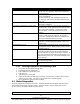
Indications:
• Problems moving just one axis, including hard turning in one or both directions.
Servo Types:
• X and Y servos are identical
Objective:
• Isolate the problem to the particular Servo Driver
Steps:
1. Turn off and unplug the system.
WARNING!
Do not work with the Servo Driver unless the power is disconnected from the machine. There is
possibility of death by electrocution!
2. Physically swap the servo module from the axis that is not working to one that is.
Note: To avoid pulling the wires out of the connector, use the loop to pull the connector from the Servo
Driver.
If the problem moves to the other axis and clears up from the original axis, replace the Servo
Driver.
4.6 Glass Scales
Glass scales are used on the X and Y-axis for secondary feedback. They are optional on the
TRAK Knee mill machines. The Z glass scale comes standard with the machine.
4.6.1 Alignment of scales
• X Axis - The X-axis scale must be aligned within 0.005” in the up and down direction over
the length of the scale for proper operation. Misalignment can cause the scale to not
read in the certain areas of the scale that are not aligned with the reader head. If this
happens, the axis will mostly likely fault out in this area. Also make sure the mounting
hardware for the reader head is tight. Loose hardware can cause excess backlash when
reversing direction.
To align the scale, place a 0.001” indicator on the bed ways and on top of the scale
extrusion. Move the table along its full travel from one end to another to verify it is
aligned. If the scale is misaligned loosen the 2 screws at either end to shift the scale up
or down as needed. You will also need to loosen the center support bracket to allow the
scale to pivot.
• Y Axis - The Y-axis must be aligned in the up and down direction and must be parallel to
the Y-axis way surface. Both surfaces must be aligned to within 0.005”. Failure to align
the scale properly could cause the same problems as mentioned above. Mount your
0.001” indicator on the saddle and move the Y-axis back and forth along its travel.
• Z Axis – The Z scale must be aligned parallel with the quill. Make sure the gap on the
readerhead is consistent along the length of travel. Align the scale within 0.005” up and
down.
See Figure 28 in Section 5 for an illustration of the Z glass scales.
4.6.2 Measurements Do Not Repeat
1. Determine if the error in repeatability is random or accumulating:
• Mount a dial indicator in the quill.