
User`s manual
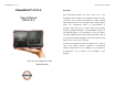

PowerBrick™ -CV 4.0 Quick Reference Manual
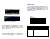
USB 2.0
Integrated 3 independent OHCI controller supporting USB
1.1 ports; Integrated 1 EHCI controller supporting USB 2.0
ports; Dynamic connection support to USB 2.0 or USB 1.1
devices
Hardware Monitor
System temperature, voltage and fan speed monitor. Auto
Thermal fan speed control
Power Management
ACPI 1.0b compliance and OS direct power management,
Wake-on event: RTC/USB
Keyboard/Modem/LAN/Keyboard/Mouse
Dimensions
7.60“X 5“ x4.13“ (W x L x H)
Power 8 ~ 30V DC
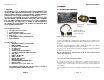
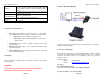
3.8 Diagnosis and maintenance
When Main Power Switch (on the back plate) is on (pilot LED is
“Red“),status LED (on the front plate) is shown two colors as following.
1. Status LED lit “ Green “ indicates that Ignition is on.
2. Status LED lit “ Blue “ indicates that Ignition is off and power
supply is normal.
Power Button LED lit “ Green “ indicates computer mother broad
running normally.
Back plate HD-LED lit flash “ Red “ indicates hand drive proper
operation and health.
Power supply fuse must be protected by a 10A auto fuse on the input
line from the vehicle battery.
3.9 Warning
Before power up the computer, make sure all cables connected to the computer
and the monitor.
WARNING
First hookup all cables then turn on computer powerSwitch.
Make sure monitor power led on or blinking .
Page 9
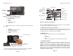
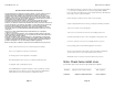
3.9A Power Brick Wiring Diagram
10A
(Computer connector : pin1-brown, pin2-green/yellow, pin3-blue, for sure power
make pi
n1 and pin3 togather)
4. CONTACT NFORMATION
With the unique set of products, Acura Embedded Systems remains committed
to its goal of providing trouble-free and customer-friendly service. A special
customer service unit has been set up specifically to cater to our esteemed
customers' needs.
Technical Support:
Phone: 1-866-502-9666
Email: support@acuraembedded.com
Mail address:
Acura Embedded Systems Inc.
Unit #1, 7711-128th Street
Surrey, BC V3W 4E6 CANADA
Ph: (604) 502-9666 Fax: (604) 502-9668
Page 10