AcuTab 2 Manual Version: 1.
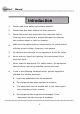
AcuTab 2 Manual Introduction 1. Please read these safety instructions carefully. 2. Please keep this Users Manual for later reference. 3. Please disconnect this equipment from connecter before Cleaning, don’t use liquid or prayed detergent for cleaning. Use moisture sheet or cloth for cleaning. 4. Make sure the equipments are connected to the power source with the correct voltage, frequency, and ampere. 5. All cautions and warnings on the equipment should be noted. 6.
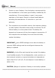
AcuTab 2 9. Manual Caution on use of battery: User the battery recommended by the manufacturer or the same type of battery installed by the manufacturer. If incorrect battery is used, it may cause explosion or fire hazard. Recycle or discard used batteries according the manufacturer ¡s instruction or your local authority. 10. The computers use nonvolatile memory that requires a battery to retain system information when power is removed. The 3V lithium battery is on the system board.
AcuTab 2 Manual Replace only with same or equivalent type recommended by the manufacturer. Discard used batteries according to the manufacturer ¡s instructions. FCC Compliance Statement This equipment has been tested and found to comply with the limits for a class B digital device, pursuant to part 15 of the FCC Rules. These limits are designed to provide reasonable protection against harmful interference in a residential installation.
AcuTab 2 Manual FCC Caution: Any changes or modifications not expressly approved by the party responsible for compliance could void the user's authority to operate this equipment. FCC RF Radiation Exposure Statement: 1. This Transmitter has been demonstrated co-location compliance requirements with Wi-Fi, Bluetooth and RFID Modules. This transmitter must not be co-located or operating in conjunction with any other antenna or transmitter. 2.
AcuTab 2 Manual EN 55022: 2006 +A1: 2007 EN 61000-3-2 : 2006 EN 61000-3-3 : 1995 + A1 : 2001 + A2 : 2005 EN 55024: 1998 + A1: 2001 + A2: 2003 (IEC 61000-4-2: 2008; IEC 61000-4-3: 2006 + A1:2007; IEC 61000-4-4: 2004; IEC 61000-4-5: 2005; IEC 61000-4-6: 2003 + A1: 2004 +A2: 2006; IEC 61000-4-8: 1993 +A1: 2000; IEC 61000-4-11: 2004) EN 60950-1: 2001 Safety of information technology equipment EN 300 328 V1.7.1: 2006 EN 301 489-17 V2.1.1: 2009 and EN 301 489-1 V1.8.1: 2008 EN 62311: 2008 This device is a 2.
AcuTab 2 Manual supplying public access to telecommunications and/or network services. This device may not be used for setting up outdoor radio links in France and in some areas the RF output power may be limited to 10 mW EIRP in the frequency range of 2454 to 2483.5 MHz. For detailed information the end-user should contact the national spectrum authority in France.
AcuTab 2 Manual Table of Contents Chapter 1 General Information................................................... 12 1.1. Introduction ............................................................................................. 12 1.2. Specification............................................................................................ 12 1.2.1. Main System.................................................................................................... 12 1.2.2. I/O Interface.....................
AcuTab 2 Manual 1.4. Dimensions.................................................................................................. 20 Chapter 2 System Setup.................................................................. 23 2.1. Exploring Your AcuTab 2............................................................................ 23 2.1.1. The front side of the AcuTab 2.......................................................... 23 2.1.2. The rear side of the AcuTab 2 .....................................
AcuTab 2 Manual 3.4. Installing the Battery (optional) ................................................................ 42 3.5. Using a SIM Card......................................................................................... 43 3.5.1. Inserting a SIM Card ........................................................................................... 43 3.5.2. Removing a SIM Card.......................................................................................... 45 3.6.
AcuTab 2 Manual 5.2.2 Hibernate this System.................................................................. 66 5.2.3 System Status Information ........................................................... 66 5.3. Using the Application................................................................................69 5.3.1 Brightness Control........................................................................ 69 5.3.2 Volume Control..................................................................
AcuTab 2 Manual Chapter 1 General Information 1 1.. Introduction AcuTab 2 semi-rugged tablet PC is IntelR Oak Trail Atom Z670 1.5GHz processor core architecture based Semi-rugged Tablet PC with a bright 10.1-inch LED backlight LCD display. The powerful CPU brings the most dynamic applications to life without sacrifices to any industrial reliability. Delivering a variety of connectivity features, built-in USBs, Microphone and Headphone port. It is ideal for an all-around system performance.
AcuTab 2 Manual IntelR Oak Trail Platform CPU : IntelR Atom Z6701.5GHz Processor packing : Micro-FCBGA Cores : Single Core On-die L2 Cache : 512KB FSB Speed : 400MHz Chipset: Chipset : IntelR Whitney Point PCH (SM35) BIOS : Phoenix BIOS Graphics : IntelR HD Graphics with dynamic frequency, support MPEG2, MEPG4, VC-1, WMV9 and H.264 System Memory : DDR II 800 (32b) Memory Down, up to 2GB Storage : 1 x 1.8-inch half-size micro-SATA Solid State Disk LCD Screen : Panel size : 10.
AcuTab 2 Manual Transflective plus type Audio : Internal Speaker : 2 x High Quality Speakers (2W) Internal Microphone : 1 x in front Bezel TPM : 1 x Compatible with TPM1.2 (option) Communication : 1 x Wireless IEEE 802.11 b/g/n 1 x Bluetooth 2.1 + EDR RFID (NFC) : Frequency : 13.56MHz ~7KHz Reading Range : within 40 ~50mm depending on type of tags HF RFID Reader : ISO/IEC 14443A/B, 15693 Mifare 1K/4K, Ultra light NFC-IP1 Protocol Webcam : Front Bezel: 1.3 Mega-pixel Camera audio input function.
AcuTab 2 Manual 1 x Docking Connector 1 x DC-Jack LED Status Indicator: Power LED Status: 1 x Green/Orange/Red Colors Storage LED Status: 1 x Blue Color Wi-Fi LED Status: 1 x Blue Color 1.2.3. In Front Control Switch : 1 x Power Button 1 x Lock Button 1 x RF Button Button : Navigation Buttons : 5+ Way navigation button with integrated enter button Program Function Buttons : 5 x Function keys (Programmable) Barcode Buttons : 2 x Trigger Buttons (Programmable) Sensor : 1 x Light Sensor 1.2.4.
AcuTab 2 Manual Internal Smart Lithium Polymer Battery, 3800mAh (2S1P), 7.4V 1.2.5. Environment Operation Temperature : 0¢C to +40¢C (MIL-STD-810G Method 501.5 and 502.5) Storage Temperature : -20¢C to +60¢C (MIL-STD-810G Method 501.5 and 502.5) Humidity : 5-90% without condensation (MIL-STD-810G Method 507.5) Drop : 4-ft drop to Plywood (MIL-STD-810G Method 516.6 Procedure IV) Vibration : Operating : SSD (MIL-STD-810G Method 514.6 Category 4 Fig 514.
AcuTab 2 Manual Dimension (W x H x D mm) : 277.8 x 206 x 26.5mm Weight : Approximate 1.2kg (with internal battery) 1.2.7. Operation OS WES7-WS7E and WES7-WS7P 1.2.8. Certifications EMI : FCC part 15 Class B VCCI (V-3/V-4) CE (EN55022 / EN55024) Safety : UL (EN60950), CE RF : FCC part 15 subpart C SAR : FCC SAR (OET 65 C) 1.2.9. Optional: Internal Module 3.
AcuTab 2 Manual GSM/GPRS/EDGS 850/900/1800/1900MHz Gobi3000 : Protocol : HSUPA/HSDPA/UMTS/EVDO/EDGE Frequency : UMTS/HSUPA/HSDPA 850/900/1800/2100MHz CDMA/EVDO 800/1900MHz GSM/GPRS/EDGS 850/900/1800/1900MHz 1.2.10.
AcuTab 2 Manual 1 x Signal Color LED (Blue) GPS/GPRS Tracker : GPRS Frequency : Quad-Band: 850/900/1800/1900Mhz Compliant to GSM phase 2/2+ Class 4 (2W @ 850/900MHz) Class 1 (1W @ 1800/1900MHz) 1 x Double Color LED (Red & Green) GPS Channel : 50 channel all-in-view tracking 1 x Double Color LED (Red & Blue) 1 x Microphone Desktop Docking : 4 x USB2.
AcuTab 2 Manual 6VDC to 36VDC Input (6VDC to 36VDC for Momentary and 9VDC to 32VDC for Normal) 19 V@1.57A Max., total output 30W Cigarette lighter plug power cord ACC power cord (option) GPS or GPS/GPRS Tracker (option) 1.2.11. Optional: Packing Lists Carrying Case Handle Secures 1 3..
AcuTab 2 Manual 21
AcuTab 2 Manual 22
AcuTab 2 Manual Chapter 2 System Setup 2 1.. Exploring Your AcuTab 2 Before starting to set up the AcuTab 2, take familiar with the locations and purposes of controls, drives, connectors and ports, which are illustrated in the figures below. When placed upright on the desktop, the front panel of the AcuTab 2 appears as shown in Figure 2.1. 2.1.1. The front side of the AcuTab 2 The front side of the AcuTab 2 is equipped the I/O as described below.
AcuTab 2 Manual 1. Camera/1.3 Mega-pixel 3. LED Power/Storage/Wi-Fi 5. Barcode Button 2. Digital Microphone 4. Light Sensor 6. Navigation Buttons 8. User Interface Button 10. Barcode Button 7. RFID 9. Program Function Buttons Camera/1.3 Mega-pixel The built-in camera can be used as a communication device for allowing you to capture images, record videos, and have video chats. It is 1.3M pixels and transmitting instant image through network for conference.
AcuTab 2 Manual Lights green when the system is powered on and battery is discharged. Lights blinking green when the system is in S3 Suspend. Lights orange when the system is powered on and battery is charging. Lights blinking orange indicates that the battery is in charging and system is power off. Lights off when power off. Lights blinking red when the Internal Battery =< 10%. ( External Battery = 0% ) Lights blinking red when the system is in S3 Suspend and the Internal Battery =< 10%.
AcuTab 2 Manual If your system does not install this module, this button can be programmable to execute specific application. When you program your application, please write this directory as listed below into your configuration file, then the system will aware and execute this application. EXE="C:\WINDOWS\system32\mspaint.exe" F5_PARA="" F5_PATH="" Barcode Buttons (Left Side) When Scanner is scanning the Barcode, please press Barcode Button simultaneously to enable this function.
AcuTab 2 Manual This button is used to define the User Interface function. When you press this button, the system will appear the UI screen as illustrated below for executing the applications easily and quickly. Programmable Function Buttons If your system does not define this button’s function, this button can be programmable to execute specific application.
AcuTab 2 Manual F2_EXE="C:\Program Files\Windows Media Player\wmplayer.exe" F2_PARA="/prefetch: 1" F2_PATH="" F3_EXE="C:\WINDOWS\system32\osk.exe" F3_PARA="" F3_PATH="" F4_EXE="C:\WINDOWS\system32\taskmgr.exe" F4_PARA="" F4_PATH="" The configuration file is "c:\FKeySet.txt" 2.1.2. The rear side of the AcuTab 2 The rear side of the AcuTab 2 is equipped the I/O as described below.
AcuTab 2 Manual 1. Camera/2 Mega-pixel 2. SIM Card/Optional Accessories Door 3. External Battery Connector 4. 5. Speaker 6. Protective Rubber Camera/2 Mega-pixel The built-in camera can be used as a communication device for allowing you to capture images, record videos, and have video chats. It is 2.0 M pixels and transmitting instant image through network for conference.
AcuTab 2 Manual Speaker Integrated left and right mini stereo speakers for sound and audio output for your multimedia presentations or listening pleasure. Protective Rubber To prevent system harm from vibration or shock, the system has been designed with installing four protective rubber at the four corner. 2.1.3. The right side of the AcuTab 2 The right side of the AcuTab 2 is equipped the I/O as described below. 1. Microphone port 2. Headphone port 3. USB port 4.
AcuTab 2 Manual Microphone port Allows you to connect an external microphone for monophonic sound recording directly into your Tablet PC. Headphone Port Lets you plug in a stereo headphone, powered speakers, or ear phone set for personal listening. USB Ports (x2) The Universal Serial Bus (USB) port allows you to connect USB 2.0-compliant devices (for example, printers, scanners and so on) to your Tablet PC. 2.1.4. The left side of the AcuTab 2 1. Power Button 2. Lock Button 3. Wi-Fi Button 4.
AcuTab 2 Manual Power Button Switches the computer power on and off, or resumes whenever it is in Suspend mode. Lock Button To prevent the screen or function keys have been touched by random, you can press the Lock button to halt the system temporarily; the screen will appear Lock message. To make the system back to work, press the Lock button again to disable the halt function, the screen will appear Unlock message.
AcuTab 2 Manual When you press the Wi-Fi Button, the screen pops-up the option list for your selection. You can see all functions in this option list have been ticked. To close any function, please touch the option to close the execution as shown in the following graphics.
AcuTab 2 Manual To activate the function, please again tick the option as shown in the following graphics to make the function enable. Activate 3G function Activate Bluetooth function Activate Wi-Fi function DC-Jack Lets you connect the AC power adapter in supplying continuous power to your Tablet PC and recharging the battery.
AcuTab 2 Manual 2.1.5. The bottom side of the AcuTab 2 1. Docking Connector Docking Connector Lets you connect the system to docking stand to dock the tablet PC when you are at home or office desk. 2. 2 . Preparing for Installation Your AcuTab 2 is designed and pre-configured for easy setup and use. This section describes the installation steps you should follow to get the system running as quickly as possible. 2.2.1.
AcuTab 2 1. 2. Manual Place the AcuTab 2 to rear side and install the rubber bumpers to the 4 corners of the system. Screws the rubber bumpers to fix them securely into the system. 2.2.2. Removing the Rubber Bumpers To remove the rubber bumpers, please place the system to rear side and unscrew the rubber bumpers of the tablet PC. 2.2.3. Plugging to the DC supply The AC adapter provides external power source to your system and charges the internal battery pack at the same time.
AcuTab 2 Manual 3. Plug the other end of the power cord to a live wall outlet, at the same time, the Power LED at face panel lights up green. -- For the power supply of this equipment, an approved power cord has to be used. -- Make sure the socket and any extension cord(s) you use can support the total current load of all the connected devices.
AcuTab 2 Manual 2.2.4. Starting Your System The Power/Resume button is found on the left side of the Tablet PC. Press the Power/Resume button to start your system and check that if the Power LED turns on. After a few seconds, the system’s display will turn on and your system will begin to execute the Power On Self Test or POST to check if all system components are running properly. Any error found during the test will be displayed on the screen.
AcuTab 2 Manual 2.2.5. Connecting the keyboard and mouse Before setting up the system, please make sure the following items are available. Keyboard Mouse (for system software installation) A keyboard is an input device; a mouse is a pointing device. Please connect these two devices as graphics shown below to interact with your system.
AcuTab 2 Manual Chapter 3 Using the AcuTab 2 3. 1 . Introduction This chapter describes the basic features and procedures for using the panel PC. It includes the I/O ports connecting and the touch screen operation. 3. 2 . Using the USB Ports USB (Universal Serial Bus) is a hardware interface that enables you to connect multiple devices (such as printers, mice, keyboards, storage devices, joysticks, digital cameras, and video conference cameras, etc.
AcuTab 2 Manual fully backward compatible, you will be able to use a USB 1.1 device in a USB 2.0 compliant system. 1. Connect the external device to the system. 2. The USB ports support hot plug-in connections. Install the device driver before using the device. 3 3.. Using the External Audio System At the right side of your Tablet PC, you will find the built-in audio ports for connecting Microphone jacks, earphone or powered speaker. To connect to an audio jack: 1.
AcuTab 2 Manual 3. 4 . Installing the Battery (optional) AcuTab 2 provides optional external battery to extend the power of your system. For installing the battery pack, please follow the steps below: 1. Turn off the system. 2. Align the hook wall at the rear side, then place and screw it fixedly. 3. Remove the cover of the external battery connector (as marked below) and place it on the lower position (as marked below).
AcuTab 2 Manual 4. Snap the battery pack into the external battery connector and hook into the hook wall securely. For removing the external battery, repeat the above steps in reverse order to remove the battery. 3. 5 . Using a SIM Card Your AcuTab 2 has a 3.5G HSDPA module that can work with SIM card. (SIM card is always working with 3.5G HSDPA PCI-E Card.) 3.5.1.
AcuTab 2 1. Manual Turn off your System. The AcuTab 2 must be powered off while the SIM Card is being connected. Otherwise, it is harmful to both devices and it shortens the life of these devices. 2. Unscrew the optional accessory cover on top of the Tablet PC. 3. Make sure the clipped corner facing inward with the metallic label of the card facing up. Push the SIM Card firmly but slowly to the SIM Card slot.
AcuTab 2 Manual 3.5.2. Removing a SIM Card To remove a SIM Card from the SIM Card slot: 1. Turn off your system. 2. Slightly push the SIM card to pop it out and pull it out directly. When the SIM card has moved out a space out of the slot, hold the edges of the card and slowly slide it out. 3. 6 . Using a Barcode Scanner Module (optional) Your AcuTab 2 is designed with equipped the optional Barcode Scanner module.
AcuTab 2 Manual To install the Barcode Scanner Module: 1. Make sure the system is turned off. 2. Unscrew the compartment cover on top of the system. 3. Screw the Barcode/MSR transfer board into the motherboard.
AcuTab 2 Manual 4. Attach the Barcode Scanner connector to the connectors inside the compartment. 5. Screw to secure the Barcode Scanner module onto the system. Barcode Scanner Module 3. 7 . Using a MSR Module (optional) Your AcuTab 2 is designed with equipped the optional MSR module.
AcuTab 2 Manual 1/2 to OFF and DIP 3/4 to ON as indicated in the following graphics. To install the MSR Module: 1. Make sure the system is turned off. 2. Unscrew the compartment cover on top of the system. 3. Screw the Barcode/MSR transfer board into the motherboard.
AcuTab 2 Manual 4. Attach the MSR connector to the connectors inside the compartment. 5. Screw to secure the MSR module onto the system. MSR Module 3. 8 . Using a Tracker Module (optional) Your AcuTab 2 is designed with equipped the optional Tracker module.
AcuTab 2 Manual 1. Make sure the system is turned off. 2. Unscrew the compartment cover on top of the system. 3. Screw the tracker transfer board into the motherboard. Tracker Transfer Board 4. Attach the Tracker connector to the connectors inside the compartment. 5. Screw to secure the Tracker module onto the system.
AcuTab 2 Manual 3. 9 . Using the Docking Stand (optional) AcuTab 2 provides optional of docking stand for you to dock this system when you are at your home or on your office desk. Docking Stand Docking Connector Attach the AcuTab 2 to the docking stand by connecting the docking connectors both on the system and the docking stand.
AcuTab 2 Manual 3.9.1. The right side of the Docking Stand 1. USB port 2. USB port The Universal Serial Bus (USB) port allows you to connect USB 2.0-compliant devices (for example, printers, scanners and so on) to your AcuTab 2.
AcuTab 2 Manual 3.9.2. The rear side of the Docking Stand The rear side of the docking stand provides the following ports and connectors as described below. 1. Locking Device Keyhole 2. USB port 3. USB port 4. HDMI port 5. VGA port 6. LAN port 7. DC-Jack Locking Device Keyhole Lets you attach a Kensington security system or a compatible lock to physically secure your AcuTab 2. USB port This docking stand lets you use USB connectors to transfer data.
AcuTab 2 Manual You can run the screen display and the external monitor simultaneously. LAN port An 10Base-T/100Base-TX Ethernet LAN module lets your AcuTab 2 connects to other computers/networks through a local area network (LAN). DC-Jack Lets you connect the AC power adapter in supplying continuous power to your system and recharging the battery.
AcuTab 2 Manual Chapter 4 The BIOS Setup Program This system comes with a chip from Phoenix BIOS that contains the ROM Setup information for your system. (This chip serves as an interface between the processor and the rest of the system components.) This section explains the information contained in the Setup program and tells you how to modify the settings according to your system configuration. The Setup utility program allows updates to the main board configuration settings.
AcuTab 2 Manual Function Key (s) Function Description To display the General Help screen To save changes and exit the BIOS SETUP UTILITY To jump to the Exit Screen or exit the current screen 4 1.. Main Screen Setup Utility When you enter the BIOS SETUP UTILITY, the Main screen will appear and display the system overview. The Standard CMOS Setup screen is displayed above. Each feature may have one or more option settings.
AcuTab 2 Manual the feature you want to change and then use value you want for that feature. or to select the NOTE: The system BIOS automatically detects BIOS, Processor, memory size, thus no changes are necessary. NOTE: The system BIOS automatically detects Phoenix, Processor, memory size, thus no changes are necessary. System Date To set the date, highlight the Date field and then press +/- keys to set the current date. Follow the month, day and year format.
AcuTab 2 Manual System Memory Speed The system will automatically displays the information of System Memory Speed. L2 Cache RAM The system will automatically displays the information of L2 Cache RAM. Total Memory The system will automatically displays the information of Total Memory. 4 2.. Advanced BIOS Features For Advanced Settings, the BIOS will automatically display the Platform information and let you define the configuration when system booting.
AcuTab 2 Manual Select Language Lets you select the language displayed in SETUP UTILITY. (The current BIOS support the languages of English, Japanese and French.) UEFI Boot Lets you activate or close the UEFI boot function by selecting Enabled or Disabled option. Legacy Boot Lets you activate or close the Legacy boot function by selecting Enabled or Disabled option. Boot Priority Lets you set the boot priority from UEFI boot or HDD boot.
AcuTab 2 Manual 4 3.. Security Chip Configuration Supervisor Password is: This option displays the status of Supervisor Password. If the password is entered, it will display Set information, or it will display Cleared information when there is no password setting. User Password is This option displays the status of User Password. If the password is entered, it will display Set information, or it will display Cleared information when there is no password setting.
AcuTab 2 Manual TPM Support Lets you activate or close the TPM function by selecting Enabled or Disabled option. (For the non-TPM SKU, this item will display no detected.) 4 4.. Boot Management Setup This page allows you to set the search drive sequence where the system will try to boot up first. To select the boot device, you can use the up or down arrow key, then press <+> to move up the device in the list or press <-> to move down the device in the list. To exit from this menu, press .
AcuTab 2 Manual 4 5.. Exit Control Exit Saving Changes When you select this option, it will pop-out the following message, Save configuration changes and exit setup? Select [OK] to save the changes and exit the BIOS SETUP UTILITY. Exit Discarding Changes When you select this option, it will pop-out the following message, Discard changes and exit setup?. Select [OK] to exit the BIOS SETUP UTILITY without saving any changes.
AcuTab 2 Manual Save Changes When you select this option, it will pop-out the following message, Save changes? Select [OK] to save all changes.
AcuTab 2 Manual Chapter 5 User Interface for AcuTab 2 5. 1 . Introduction This user interface provides specific mobile utility to let you easily setup some helpful functions and aware the system status directly. This utility also let you adjust some function to fit the requirements, such as brightness and volume adjustment, webcam launch, screen orientation and monitor switching.
AcuTab 2 Manual To close the User Interface function, please press the button on the top right corner on this User Interface for disabling this utility from the screen. If there is no action took for this utility in 5 seconds, the UI screen will close automatically.
AcuTab 2 Manual 5.2.2 Hibernate this System If you want to hibernate this system, please click button for entering into S4 mode. 5.2.3 System Status Information This utility shows you the battery capacity status, RF status with its signal strength and system information, and provides the control panel for the function setting.
AcuTab 2 Manual For battery capacity status: The AcuTab 2 is equipped with one internal battery and one optional battery. The battery capacity status shown below advises you, that only one internal battery is embedded with the system with fully charged, and there is no optional battery installed in the system. If the system installs both the 1st internal battery and 2nd optional battery, the graphics shown below indicates the charging status.
AcuTab 2 Manual If 1st battery capacity is down to 15%, the system will display the following warning message for 5 seconds For RF status: The following RF status shows you that the system is equipped with Wi-Fi, Bluetooth, and 3G functions. Moreover, there are optional modules for RFID and GPS. If you want to close either of these functions, please see section for how to re-set it up.
AcuTab 2 Manual will show on the bar. If there is no module in the system, there will be no status scale in the following status bar. For System Information: The system information shown on the left advises you the utility version, BIOS and EC version and you can use them for customer service. 5. 3 . Using the Application Your AcuTab 2 has numbers of applications on the control panel for executing specific command.
AcuTab 2 Manual When you press it, the brightness control panel is appeared as follows: You can click or to reduce or increase the brightness. to set the Also, you can slide the scale bar brightness. Since the system supports the light sensor, if you tick the brightness Auto adjustment , the screen brightness will automatically adjust according to the operating environment.
AcuTab 2 Manual 5.3.2 Volume Control For Volume adjustment, press the Volume command. When you press it, the Volume control panel is appeared as follows: You can click or to reduce or increase the audio volume incrementally. Also, you can slide the scale bar to set the audio volume. You can tick the Mute to make the system voiceless.
AcuTab 2 Manual 5.3.3 Webcam Launch For Webcam Launch, press the Webcam command to appear the Webcam utility for your application. 5.3.4 Monitor Switch For Monitor switch, press the Monitor Switch to pop-up the selection bar for choosing the display mode within following four options.
AcuTab 2 Manual You can click Computer only to display the AcuTab 2 screen only. You can click Duplicate to display the same contents both on the AcuTab 2 screen and external display device. The resolution on these two display modes are same, it is not available to adjust the resolution on the external display mode. You can click Extend to display the different contents on the AcuTab 2 screen and external display device. You only can adjust the resolution on the external display device.
AcuTab 2 Manual Chapter 6 Maintenance Your AcuTab 2 needs occasional cleaning to prolong their life. Please read this section carefully to ensure proper care of AcuTab 2. When it is necessary to clean it, use a soft, lint-free cloth, slightly dampened with a mild detergent solution or use the contents of any commercially available computer cleaning kit. Never use petroleum-based solvents, or harsh detergents to clean the system. Also never spray any liquids directly on the computer case or screen.
AcuTab 2 Manual Dispose of used batteries according to local regulations. 6. 2 . Maintaining the LCD Display Do not scratch the surface of the screen with any hard objects. Do not spray liquid directly on the screen or allow excess liquid to drip down inside the device. Do not place anything, such as food and drink, on the screen at any time to prevent damage to the screen. Clean the LCD display only with a soft cloth dampened with denatured alcohol or a proprietary LCD screen cleaner. 6. 3 .