AcuPanel 12 User Manual AcuPanel 12 User Manual Version 7.1 Acura Embedded Systems Inc.
AcuPanel 12 User Manual Copyright Copyright© 2011 All Rights Reserved - Printed in Acura Embedded Systems Inc Disclaimer Acura Embedded Systems Inc shall not be liable for technical or editorial errors or omissions contained herein; nor for incidental or consequential damages resulting from using this material, or the performance or use of this product. Acura Embedded Systems Inc reserves the right to change product specifications without notice. Information in this document may change without notice.
AcuPanel 12 User Manual INDEX Table of Contents ........................................................................ 2 2.2. Installation Procedures ...........................................................9 2.2.1. Connecting the power cord ...................................................10 2.2.2. Connecting the keyboard and mouse ...................................10 2.2.3. Switching on the power .........................................................11 Chapter 1 General Information ........
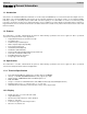
AcuPanel 12 User Manual Chapter 1 General Information 1.1. Introduction AcuPanel12 is an embedded Intel® Cedar Trail Dual Core 1.6 Ghz +Chipset: Intel® NM10 processor based Panel PC with a bright 10.4”/12.1" LCD display. The powerful Intel® NM10 chipsets bring the most dynamic applications to life without sacrifices to any industrial reliability. Delivering a variety of connectivity features, built-in USB and robust capacity of 2.5” SATA HDD, it is ideal for an all-around system performance.
AcuPanel 12 • • User Manual Viewing Angle: 12.1" 80° (left), 80° (right), 80° (up), 80° (down) Lamp Life Time: 50,000 hours 1.3.3. Touch Screen • • • Touch Screen type: 5-wire Analog resistive type Light Transmission: 80% Durability (Touch lifetime): 35 million 1.3.4. I/O Interface • • • • • Serial Port: 2 x Serial port USB Port: 2 x USB 2.0 ports LAN Port: 1 x RJ45 Connector for 10/100/1000 Base T Ethernet Front LED: PWR / HDD Switch: Power button 1.3.5.
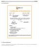
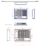
AcuPanel 12 User Manual 1.3.9. Certifications 1.4. Physical Dimensions Your panel PC is equipped with fanless and no-ventilation-hole design and is durable to suit any critical environment. The following drawing shows you detailed information for the dimensions.
AcuPanel 12 User Manual Dimensions (units in mm) 6
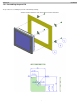
AcuPanel 12 User Manual 1.4.1. Assembling the panel PC The procedure for assembling the panel PC is identified by following drawing. Please follow the instruction below for panel mounting.
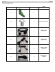
AcuPanel 12 User Manual 1.4.2. Enclosed Parts ITEM PARTS QTY SPEC 4 A M6*1.0+15PF-SUS B 4 C 1 RJ45, L=1.8M (Optional) D 2 DSUB, L=1.8M (Optional) E 2 USB, L=1.8M (Optional) F 1 DC Extension, L=1.
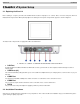
AcuPanel 12 User Manual Chapter 2 System Setup 2.1. Exploring AcuPanel 12 Before starting to set up the panel PC, take familiar with the locations and purposes of controls, drives, connectors and ports, which are illustrated in the figures below. When placed upright on the desktop, the front panel of the panel PC appears as shown in Figure 2.1. The bottom side of the panel PC is equipped the I/O as described below. 1. LAN Port 2. USB2.0 3. USB2.0 4. RS-232/422/485 5. RS-232 6.
AcuPanel 12 User Manual 2.2.1. Connecting the power cord To connect the power cord: 1. Connect the DC extension cable plug to the computer’s Power Supply Connector. 2. Connect the DC extension cable wires to the corresponding positive and negative terminals on the DC power supply. 3. Turn on the DC power supply. HAZARD OF ELECTRIC SHOCK, EXPLOSION OR ARC FLASH • • • • • Remove all power from the device prior to installing or removing any accessories, hardware, or cables.
AcuPanel 12 User Manual 2.2.3. Switching on the power The Power button is found on the left bottom on the rear side of the Panel PC. Press the Power button to start AcuPanel12 and check that the Power LED lights on to green on the front panel. Chapter 3 Using the Panel PC AcuPanel12 is designed and pre-configured for easy setup and use. This chapter describes the installation steps you should follow to get the system up and running as quickly as possible. 3.
AcuPanel 12 User Manual 3. Turn on any other peripheral devices which are connected to the panel PC, and then turn on the panel PC. 4. Refer to the manual(s) which accompanied any serial device(s) for instructions on configuring the operating environment to recognize the device(s). 5. Run the BIOS setup program and configure the jumper settings to change the mode of the COM ports. 3.
AcuPanel 12 User Manual 3.5. Touchscreen AcuPanel12 is designed using Color Active Matrix LCD technology with a high quality touch sensitive surface. The touch screen is a display that can detect the presence and location of a touch within the display area by a finger, hand or other passive objects, such as a stylus. It enables one to interact with what is displayed directly on the screen, rather than indirectly with a mouse.
AcuPanel 12 4.4.Chipset Features 4.5.Boot Features User Manual This option lists all the features for chipset configuration. This option lists all onboard bootable devices. 4.6.Security Management Setup Set Administrator/User Password, These options let you create, change or disable the passwords.
AcuPanel 12 User Manual 4.7.Save & Exit Setup This option lets you saves all changes to CMOS while running the BIOS setup program and exit from the system setup program. WARNINGS THIS EQUIPMENT IS SUITABLE FOR USE IN CLASS I, DIVISION 2, GROUPS (AS APPLICABLE) OR NON-HAZARDOUS LOCATIONS ONLY. WARNING - EXPLOSION HAZARD - SUBSTITUTION OF COMPONENTS MAY IMPAIR SUITABILITY FOR CLASS I, DIVISION 2.
AcuPanel 12 User Manual With the unique set of products, Acura Embedded Systems remains committed to its goal of providing trouble-free and customer-friendly service. A special customer service unit has been set up specifically to cater to our esteemed customers' needs. Technical Support: contact your Salesperson or support@acuraembedded.com Mailing address: Acura Embedded Systems Inc.