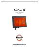
AcuPanel 12 User Manual AcuPanel 12 User Manual Version 5.1 Acura Embedded Systems Inc.
AcuPanel 12 User Manual Copyright Copyright© 2011 All Rights Reserved - Printed in Acura Embedded Systems Inc Disclaimer Acura Embedded Systems Inc shall not be liable for technical or editorial errors or omissions contained herein; nor for incidental or consequential damages resulting from using this material, or the performance or use of this product. Acura Embedded Systems Inc reserves the right to change product specifications without notice. Information in this document may change without notice.
AcuPanel 12 User Manual INDEX Table of Contents ........................................................................ 2 Chapter 1 General Information .................................................. 3 1.1. Introduction ............................................................................3 1.2. Features ..................................................................................3 1.3. Specification ...........................................................................3 1.3.1.
AcuPanel 12 User Manual Chapter 1 General Information 1.1. Introduction AcuPanel12 is an Intel® Celeron M 1.0G /512K or Intel® Atom N450 processor based Panel PC with a bright 10.4”/12.1" LCD display. The powerful Celeron M CPU with Intel® 915GME/910GMLE + ICH6M chipsets or Atom N450 CPU with ICH8M chipsets bring the most dynamic applications to life without sacrifices to any industrial reliability. Delivering a variety of connectivity features, built-in USB, Mini PCI-E socket, and robust capacity of 2.
AcuPanel 12 • • User Manual Viewing Angle: 12.1" 80° (left), 80° (right), 80° (up), 80° (down) Lamp Life Time: 50,000 hours 1.3.3. Touch Screen • • • Touch Screen type: 5-wire Analog resistive type Light Transmission: 80% Durability (Touch lifetime): 35 million 1.3.4. I/O Interface • • • • • • • Serial Port: 2 x Serial port (COM1:RS-232, COM2:RS-232/422/485 select by jumper) USB Port: 2 x USB 2.
AcuPanel 12 User Manual Software Support: Microsoft Windows XP Professional for Embedded, XP Embedded. 1.3.10. Certifications 1.4. Wall Mounting Installation(Option) 1.4.1. Physical Dimensions Dimensions (units in mm) 1.4.2.
AcuPanel 12 User Manual Stud Walls 6
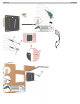
AcuPanel 12 User Manual 1.4.3. Display Installation Process Mount display brackets to the back of the display Install the Display onto the wall mount bracket 1.4.4. Enclosed Parts ITEM A B C D E F 4 PLUG 07 L35 4 SCREW K P3/16” 11/2” 4 SCREW PSW M4 L14 WNi 4 SCREW PSW M4 L10 WNi PARTS QTY SPEC 1 1 Please refer to 1.4.1 WARNGING:The maximum display weight the Wall mount bracket can support is below 25Kg.(55lbs).
AcuPanel 12 User Manual Dimensions (units in mm) 8
AcuPanel 12 User Manual 1.5.2. Assembling the panel PC The procedure for assembling the panel PC is identified by following drawing. Please follow the instruction below for panel mounting.
AcuPanel 12 User Manual 1.5.3. Enclosed Parts ITEM PARTS QTY SPEC 4 A M6*1.0+15PF-SUS B 4 C 1 RJ45, L=1.8M (Optional) D 2 DSUB, L=1.8M (Optional) E 2 USB, L=1.8M (Optional) F 1 DC Extension, L=1.
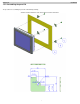
AcuPanel 12 User Manual 1.6. Stand Installing Instruction(Option) 1.6.1. Physical Dimensions Your panel PC is equipped with stand to fit your flexibility and necessity and let you execute your system comfortably. The following drawing shows you detailed information for the dimensions. SPECIFICATIONS Max. wall mount hole pitch Screw type Material Dimension(W*H*D) Weight Tilt Support max. weight 75*75mm M4 Steel/Aluminum 203.1*227.2*167.5 mm 1.
AcuPanel 12 User Manual 1.6.2. Stand Installation To install the stand into AcuPanel12 System: 1. Align the hole on the stand to the hole on the rear side of AcuPanel12 system. 2. Then stick them by rotating and tightening the screws securely and firmly. After the stand is installed to the system, please find the dimension for different angles as listed below.
AcuPanel 12 Dimensions in Front View User Manual Dimensions in Side View Dimensions in Top View 13
AcuPanel 12 User Manual Chapter 2 System Setup System Setup 2.1. Exploring AcuPanel 12 Before starting to set up the panel PC, take familiar with the locations and purposes of controls, drives, connectors and ports, which are illustrated in the figures below. When placed upright on the desktop, the front panel of the panel PC appears as shown in Figure 2.1. The bottom side of the panel PC is equipped the I/O as described below. 1. LAN Port 2. USB2.0 3. USB2.0 4. RS-232/422/485 5. RS-232 6.
AcuPanel 12 User Manual 2.2. Preparing for First-time Use Before setting up the system, please make sure the following items are available. • Keyboard & Mouse (for system software installation) 2.3. Installation Procedures Your Panel PC is designed and pre-configured for easy setup and use. This section describes the installation steps you should follow to get the system running as quickly as possible. 2.3.1. Connecting the power cord To connect the power cord: 1.
AcuPanel 12 User Manual 2.3.2. Connecting the keyboard and mouse A keyboard is an input device; a mouse is a pointing device. Please connect these two devices as graphics shown below to interact with your panel PC. 2.3.3. Switching on the power The Power button is found on the left bottom on the rear side of the Panel PC. Press the Power button to start your panel PC and check that the Power LED lights on to green on the front panel. 2.4.
AcuPanel 12 User Manual Chapter 3 Using the Panel PC Your panel PC is designed and pre-configured for easy setup and use. This chapter describes the installation steps you should follow to get the system up and running as quickly as possible. 3.1 Introduction This chapter describes the basic features and procedures for using the panel PC. It includes the I/O ports connecting and the touch screen operation. 3.
AcuPanel 12 User Manual 3.4 Using the USB Ports An external USB device may be connected to the system through the 4-pin USB ports located on the bottom side of the system unit. 1. Connect the external device to the system. 2. The USB ports support hot plug-in connections. Install the device driver before using the device. 3.
AcuPanel 12 User Manual 3.6. Touchscreen AcuPanel12 is designed using Color Active Matrix LCD technology with a high quality touch sensitive surface. The touch screen is a display that can detect the presence and location of a touch within the display area by a finger, hand or other passive objects, such as a stylus. It enables one to interact with what is displayed directly on the screen, rather than indirectly with a mouse.
AcuPanel 12 User Manual 5. Connect the cable to HDD and attach the holder to new hard disk. Make sure the holders are fixed to the HDD securely. Caution: When fix holder to HDD, please be sure that the long end should be positioned nearly to the HDD cable. 6. Locate the HDD module slightly into the compartment firmly. 7. Cover the lid, then rotate and tighten the screws. 8. Set the boot device as CD-RW Combo drive and Primary Master as Auto on BIOS setup menu.
AcuPanel 12 User Manual Chapter 4 The BIOS Setup Program The This system comes with a chip from Award BIOS that contains the ROM Setup information for your system. (This chip serves as an interface between the processor and the rest of the system components.) This section explains the information contained in the Setup program and tells you how to modify the settings according to your system configuration. 4.1.
AcuPanel 12 User Manual • Save & Exit Setup This option lets you saves all changes to CMOS while running the BIOS setup program and exit from the system setup program. • Exit Without Saving This option allows you to discard all changes made while running the BIOS setup program and exit from the system setup program. 4.2. Standard CMOS Features The Standard CMOS Setup screen is displayed below. Each feature may have one or more option settings.
AcuPanel 12 User Manual Video This field lets you set the type of video display card installed in the system. Press "Enter" for automatic device detection. Halt On This field determines which types of errors will cause the system to halt. Base Memory This field displays the amount of base (or conventional) memory installed in the system. Extended Memory This field displays the amount of extended memory (above 1 MB inCPU ís memory address map) installed in the system.
AcuPanel 12 User Manual Gate A20 Option This item allows the user to control the Gate A20 by chipset or keyboard controller with setting the option to Fast or Normal. Typematic Rate Setting This item allows you to activate or close the "Typematic Rate Setting" function. Typematic Rate (Chars/Sec) This item controls the speed at which the system registers auto repeated keystrokes. The options for settings are: 6, 8, 10, 12, 15, 20, 24 and 30.
AcuPanel 12 User Manual On-Chip Frame Buffer Size This item allows you to select the memory buffer for on-chip graphics. Boot Display This item allows you to select the display mode in booting. Panel Type This item allows the user to define the panel resolution. 4.5. Integrated Peripherals OnChip IDE Device This item enables users to set the OnChip IDE device status, including IDE devices and setting PIO and DMA access modes.
AcuPanel 12 User Manual 4.5.1. OnChip IDE Device The Setup utility program allows updates to the system configuration settings. The BIOS setup values will be saved in the CMOS. It is executed when you change the system configuration, you change the system backup battery, or the system detects a configuration error and asks you to run the Setup program. Use the arrow keys to select, and press Enter to run the selected program.
AcuPanel 12 User Manual SATA port Lets you specify the "P0,P2 is Primary" mode. 4.5.2. Onboard Device USB Controller This field lets you activate or close the onboard USB 1.0 feature. The options are: "Disabled" and "Enabled". USB 2.0 Controller This field lets you activate or close the onboard USB 2.0 feature. The options are: "Disabled" and "Enabled". USB Keyboard Support This field lets you activate or close the USB Keyboard Support. The options are: "Disabled" and "Enabled".
AcuPanel 12 User Manual Onboard Serial Port 1 This field lets you modify your serial port parameters, when the serial port uses the onboard I/O controller. The options are: "Disabled", "3F8/IRQ4", "2F8/IRQ3", "3E8/IRQ4" and "2E8/IRQ3". Onboard Serial Port 2 This field lets you modify your serial port parameters, when the serial port uses the onboard I/O controller. The options are: "Disabled", "3F8/IRQ4", "2F8/IRQ3", "3E8/IRQ4" and "2E8/IRQ3".
AcuPanel 12 User Manual This option will cause the system to turn off vertical and horizontal synchronization ports and write blanks to the video buffer Blank Screen This option only writes blanks to the video buffer. DPMS This option Initialize display power management to signalize. Video Off In Suspend This item allows you to turn off the video when the system enters into suspend mode. The options are: "No" and "Yes". Suspend Type This item allows you to determine the suspend type.
AcuPanel 12 User Manual 4.8. PC Health Status CPU Warning Temperature The feature’s options are Disable or Enable. CPU Warning Temperature Information is provided by the BIOS on this motherboard. It is not user-configurable. Current System Temp / Current CPU1 Temperature / Fan1 Speed / Fan2 Speed / Vcore / +12V / VCC (V) / VBAT (V) / 5VSB (V) Smart Fan2 Temperature This item lets you set the parameter to "Disabled", "40°C/104°F", "45°C/113°F" or "50°C/122°F".
AcuPanel 12 User Manual The two options on the main menu allow you to restore all of the BIOS settings to the default Fail-Safe or Optimized values. The Optimized Defaults are the default values set by the motherboard manufacturer, it is specific for optimal motherboard performance. The Fail-Safe Defaults are the default values set by the BIOS vendor for stable system performance. This submenu is selected for default settings with provide the best system performance. 4.11.
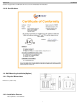
AcuPanel 12 JP1: (5-6) short CMOS: CMOS clear connector Normal: (1-2) short-default User Manual JP2: (3-5) short JP3: (4-6) short CMOS clear: (2-3) short Internal Connector CF_SEL: CF-Card device select Master: (1-2) Short-Default Slave: (2-3) Short MPCIE: PCIE Connector WARNINGS THIS EQUIPMENT IS SUITABLE FOR USE IN CLASS I, DIVISION 2, GROUPS (AS APPLICABLE) OR NON-HAZARDOUS LOCATIONS ONLY. WARNING - EXPLOSION HAZARD - SUBSTITUTION OF COMPONENTS MAY IMPAIR SUITABILITY FOR CLASS I, DIVISION 2.
AcuPanel 12 User Manual With the unique set of products, Acura Embedded Systems remains committed to its goal of providing trouble-free and customer-friendly service. A special customer service unit has been set up specifically to cater to our esteemed customers' needs. Technical Support: contact your Salesperson or support@acuraembedded.com Mailing address: Acura Embedded Systems Inc.