AcuBrite 21-Nav Manual ACUBRITE™ 21-Nav USER MANUAL ACUBRITE 21-Nav Monitor (2nd Edition 05/25/2012)
AcuBrite 21-Nav Manual TABLE OF CONTENT TABLE OF CONTENT ......................................................................................................................... 1 1.0 INTRODUCTION................................................................................................................................ 3 2.0 CONTROL AND FEATURES .......................................................................................................... 4 3.0 INSTALLATIONS............................
AcuBrite 21-Nav Manual IMPORTANT INFORMATION EMC conformance All Acura Embedded System products are designed to the best industry standards for use in the recreational environment. The design and manufacture of Acura’s equipments and accessories conform to the appropriate Electro Magnetic Compatibility (EMC) standards, but correct installation is required to ensure that performance is not compromised.
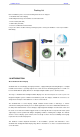
AcuBrite 21-Nav Manual Packing List Before installation, please ensure the following items have been shipped: 1 x Acubrite21-Nav Series Display 4 x Mounting bracket lugs and 4 stainless steel threaded studs 1 x Power Cable (5000 mm) 1 x VGA Cable (3000 mm) 1 x CD for User Manual and Touch Driver If any of these items should be missing or damaged, please contact your distributor or sales representative immediately. 1.
AcuBrite 21-Nav Manual 2.0 CONTROL AND FEATURES Your Acubrite 21-Nav Sunlight Viewable Display has the following controls and features: Front View Remarks: The PIP function is only available for ACUBRITE 21-Nav model Back View 3.0 INSTALLATIONS It is important that your new display is installed and operated in accordance with the instructions provided in this handbook. Failure to do so could result in poor product performance and may invalidate your warranty.
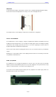
AcuBrite 21-Nav Manual IMPORTANT: Your Acubrite21-Nav display is only waterproof from the front. To maintain watertight integrity the display must be flush mounted ensuring that the rear casing is enclosed in a watertight enclosure. The Acubrite 21-Nav ™ Series Display is designed to be mounted in two configurations: VESA75 / VESA100 MOUNT The Acubrite21-Nav ™ Series Display is designed compatible with VESA75 and VESA100 mount.
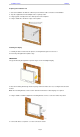
AcuBrite 21-Nav Manual Preparing the installation site 1. Select an installation site that has sufficient space behind for cable connections and ventilation. 2. Tape the supplied flush mount template in the required position. 3. Using a jigsaw, carefully remove the shaded portion of the template. 4. Using a suitable file, smooth the edges of the aperture. Installing the display 1.
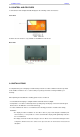
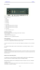
AcuBrite 21-Nav Manual Rear connections Remarks: The photo above will differ for different model The rear connectors are: 1. FUSE 2. Power Input 3. DVI-1 Input 4. DVI-2 Input 5. VGA-1 Input 6. VGA-2 Input 7. CVBS-1 Input (Composite Video) for AV input 8. CVBS-2 Input (Composite Video) for AV input 9. CVBS-3 Input (Composite Video) for AV input 10. RS232 Input 11.
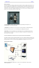
AcuBrite 21-Nav Manual Power connections The power connection to the display should be made at either the output of the battery isolator switch, or at a DC power distribution panel. Acubrite21-Nav recommends that power is fed directly to the display via its own dedicated cable system and MUST be protected by a thermal circuit breaker or fuse, fitted close to the power connection.
AcuBrite 21-Nav Manual 4.0 TOUCH DRIVER INSTALLATIONS Both AR glass and Resistive touch screen solutions are used for our products. If you have a customized or tailored product, please check the specifications in this manual or provide us your third-party specifications. Resistive Touch Screen It generally uses a display overlay composed of layers, each with a conductive coating on the interior surface.
AcuBrite 21-Nav 1.Put the TouchKit CD to CD-ROM. Manual 2.Change directory to Win9X_ME 3.Double click the Setup.exe , then windows starts to run the installation program. Notice that do not plug the USB controller on the system before the installation has been finished. 4.Just click [Next >] button to continue installation. 5.Then check the check box if PS/2 touch controller is to be installed. The default is unchecked. Then Press [Next >] to continue installation.
AcuBrite 21-Nav Manual 7.Select the appropriate folder where set-up files will be installed. Then Press [Next >] to continue installation. 8.Then type in the name of program folder for TouchKit or press [Next >] to continue. There will be a default name for it. During driver installation, the setup program will scan COM port for RS232 Touchkit controller. Once the controller was scanned, the setup program will display a dialog as Click Yes to add the controller on the specified COM port automatically.
AcuBrite 21-Nav Manual Configuration Utility and Right Button Emulator There are five property pages in TouchKit utility, and they are General, Setting,Edge coefficient, Monitors and About . Each property page contains different functions for users to do the adjustments. Therefore, users can easily manage all the TouchKit controllers through TouchKit utility. General General property page contains the functions of language selection, devices add/ remove, 4 points calibration, Draw test and Advanced .
AcuBrite 21-Nav Manual / Please check the touch panel devices (including its controller) are equipped well, Then click [Add] button to add all of those RS-232 and PS/2 devices to the Panel List dialogue box . There is one devices found. Press [Yes] to continue. The controller is displayed on the Panel List box. Users can get the information of interface, type, firmware version and baud rate for each controller. Select one device after added more than one device at the panel list window.
AcuBrite 21-Nav Manual <4pts Cal> Correct 4 point locations on screen with the panel. Press [4 pts Cal], screen displays as follows. Touch the blinking symbol on panel until beep or stop blinking. Test the drawing position related to the display screen on panel. Click on the [Draw Test] button. There will be a squared blue display showing. In drawing test window, users can click [Clear] button to clear the window.
AcuBrite 21-Nav Manual Press [25ptCal] to do 25 points calibration. Correct 25 point locations on screen with the panel. Touch the blinking symbol on panel until beep or stop blinking. After the calibration, the new record will overwrite the old one.
AcuBrite 21-Nav Manual Users could choose to make no soun d while using the touch panel. The system will make a sound while touching the panel. The system will not make any sound until finger leaves the touch panel. Sound frequency, drag the cursor from left to right is low to high. Sound duration, drag the cursor from left to right is short to long. The Mouse Mode provides users different operating options.
AcuBrite 21-Nav Manual There are five modes in shutdown utility for user convenience. [Standby] to enter standby mode that saves power consumption. [Shutdown] to turn off PC. [Reboot] to restart PC. [Cancel] to escape from the Shutdown utility dialog. [Exit] to disable the Shutdown utility. Please notice that Windows NT does not support this function. There are three kinds of mouse mode users could choose, [Normal Mode] It provides all the mouse functions, including the dragging function.
AcuBrite 21-Nav Manual If users want to cancel the function of TouchKit Hide Cursor, do the steps again and choose the other scheme. The Double Click adjustment provides users to set up the tolerance while double clicking. They are as follows : Double Click Speed is the double click response time for Windows system. Users can adjust the proper double click for easy double click by touch panel.
AcuBrite 21-Nav Manual In some case, if it is difficult to touch items at the edges of the touch panel, users can set adjustment to reach the edges of the screen image. If users set the Edge to , TouchKit will reduce the horizontal position of the top edge. If users set the Edge to , TouchKit will extend the horizontal position of the top edge. If users set the Edge to , TouchKit will reduce the horizontal position of the bottom edge.
AcuBrite 21-Nav Manual Users can choose Edge compensation Enable / Disable from left bottom corner of Touchkit Utility. Using +10% and -10% button to adjust the smaller or larger of edge. If users press +10% button, the top, bottom, left and right edges will extend 10% of orientation to touch screen, and cursor will be moved 10 pixel of X and Y Axis to right and top.
AcuBrite 21-Nav Manual To use the Split Monitor function, users need to select which controller you want to launch this function, then check the Multiple Monitors box and Split Monitor at the same time as showing as the follow picture. Press the [Split Setting] button to set up the activate area. It shows the current resolution of display and users can set up the activate area by inputting the value by yourself or use the default button [Upper Half], [Left Half] or [Quarter].
AcuBrite 21-Nav Manual MONITOR ROTATION SETTING TouchKit driver package for Windows 98/ME/2000/XP provides two easiest ways to rotate the touch panel while the display is rotated. Rotating display by way of nVidia or ATI driver Rotating display by way of Pivot. 4.1 Rotating display by way of nVidia or ATI driver 1. After activating the rotation of nVidia or ATI driver, there will be one blinking symbol show as the following picture.
AcuBrite 21-Nav Manual 4. However 180 degree rotation of touch panel can not be done in one step, users need to rotate 90 degree twice. < Rotating display by way of RotTray icon provided by TouchKit> 1. To rotate the display, please install Pivot pro 6.05 first. Then reboot PC to Activate Pivot. 2. Users will see RotTray icon in the task bar. 3. Clicking on RotTray, it will call Pivot to rotate the display and touch panel 90 degree at the same time.
AcuBrite 21-Nav 8. Here below are the value data for different version of Pivot: Manual Follow these steps to uninstall TouchKit. 1.G o to Start / Programs / TouchKit / Uninstall , and exe cute it. 2. TouchKit setup dialog appears, and prepares to uninstall. 3. Confirm dialog, press [OK] to start un-installation; [Cancel] to cancel uninstallation. 4. Start to uninstall TouchKit. If users do not want to uninstall TouchKit at this moment, press [Cancel] to terminate the uninstall process. 5.
AcuBrite 21-Nav Manual 5.0 OSD OPERATIONS Introduction Your Acubrite 21-Nav Sunlight Viewable display can be controlled using the On Screen Display (OSD) menu and/or the 8 buttons on the front bezel of the unit. The OSD menu enables you to change the way in which your display is set up and is accessed using the Menu button. Using the buttons Each of the 8 buttons on the front bezel of your display has an input and a control function.
AcuBrite 21-Nav Manual If you keep pressing “BRIGHTNESS” Key and hold it, the brightness will appear as following status: . . . .2 1 2 3 . . . 48 49 50 49 48 .... And if you release the “BRIGHTNESS” Key around 5 seconds with any action, the brightness bar will disappear. When you press “BRIGHTNESS” Key and other Key (not including Up/Down Key), the BRIGHTNESS status bar image will disappear.
AcuBrite 21-Nav Manual INPUT KEY When you press “INPUT” KEY, the screen will pop up the following image: You can press the “UP”/ ”DOWN” KEY for the menu item selection above. It will remain at “VIDEO 3” position if you keep pressing “DOWN” KEY to the end. And it will also remain at “RGB1” position if you keep pressing “UP” KEY to the end. When you press and hold the “INPUT” KEY, the menu screen will show as .... RGB1 RGB2 . . VIDEO3 VIDEO2 . .
AcuBrite 21-Nav Figure 1 Manual Figure 2 Figure 3_1 Figure 3_2 Figure 3_3 When you enter the “PIP Port Change” screen, the status bar will remain at “OFF” position if you keep pressing the “DOWN” KEY to the end. At the other hand, the status bar will remain at top item of each menu if you keep pressing the “UP” KEY to the end.
AcuBrite 21-Nav Manual MENU KEY When you press “MENU” KEY, the Acubrite 21-Nav OSD main menu screen will appear as below: If you release the “MENU” KEY for 30 seconds without any action, the menu OSD screen will disappear automatically. You can also choose “QUIT” and then press “MENU” KEY to exit this OSD menu screen.
AcuBrite 21-Nav Manual DVI 1 & 2’s setting screen: DVI Setting Item Description: · CONTRAST Contrast Adjustment R_LEVEL Red Color level Adjustment G_LEVEL Green Color level Adjustment B_LEVEL Blue Color level Adjustment TEMPERATURE Color Temperature Adjustment DISP MODE EXIT FULL Full Screen EVEN Half Screen NORMAL Keep normal aspect ratio Quit from current setting VIDEO 1 & 2 & 3’ setting screen: VIDEO Setting Item Description: CONTRAST Contrast SHARPNESS
AcuBrite 21-Nav Manual PIP Sub-menu setting screen: PIP Setting Item Description: PIP_SIZE CONTRAST Contrast Adjustment R_LEVEL Red Color level Adjustment G_LEVEL Green Color level Adjustment B_LEVEL Blue Color level Adjustment EXIT Picture in Picture Screen Size Adjustment Quit from current setting OSD Setting Main Screen: OSD Setting Item Description: H_POSITION Horizontal Screen Adjustment V_POSITION Vertical Screen Adjustment TRANSLUCENT Screen background c
AcuBrite 21-Nav Manual Programmable OSD Source Tag setting screen: 1. Press the “RIGHT/LEFT” key to selected channel 2. Press the “MENU” key to rename the “RGB1” to any desired source input (ex. Sonar, Radar…etc). You may press “RIGHT/LEFT” key to select from (A~Z, 0~9, “.”, “-“) character. If done, just press “MENU” key to jump to next character for renaming step by step. 3.
AcuBrite 21-Nav Manual SYSTEM RETURN setting screen: You may choose “SYSTEM RETURN” selection item on the OSD Screen to restore all of the parameter setting to factory default value. When you press “UP” or “RIGHT” KEY, the parameter will show “YES” and confirm it.
AcuBrite 21-Nav Manual “KEY LOCK” Mode Function setting screen: When you press “MENU” and “BRIGHTNESS” KEY simultaneously for 3 seconds, you will enter the “KEY LOCK” mode. At the same time, the screen will show “KEY LOCK” image as below for 5 seconds and then disappear. In the “KEY LO CK” mode, it will be no function to press any key. When you press the key in the “KEY LOCK” mode, the screen will show “KEY LOCK” image as below for 5 seconds and then disappear.
AcuBrite 21-Nav Manual 6.0 TECHNICAL SPECIFICATION 6.1 Specification- ACUBRITE 21-Nav LCD Display Backlight 21.5" LED Backlight Active Display Area 476.64 x 268.11 mm Brightness 1000 cd/m2 * Resolution 1920x1080 (FHD) Contrast Ratio 1000:1 Pixel Pitch (mm) 0.248(H) x 0.248 (V) Viewing Angle 170 (H), 160(V) Display Color 16.
AcuBrite 21-Nav Manual 6.
AcuBrite 21-Nav Manual 7.0 MAINTENAINCE AND TROUBLESHOOTING Precautions To maximize the life and safe use of your unit, always be sure to follow the warnings, precautions and maintenance recommendations in this user’s guide. In a Watercraft or Vehicle: The monitor should be visible to the driver only if it is used for navigation, or system control. Care should be taken to ensure distraction does not occur.
AcuBrite 21-Nav Manual Troubleshooting All products are, prior to packing and shipping, subjected to comprehensive test and quality assurance programs. However, if this unit should develop a fault, please refer to the following table to identify the most likely cause and the corrective action required to restore normal operation.
AcuBrite 21-Nav Manual With the unique set of products, Acura Embedded Systems remains committed to its goal of providing trouble-free and customer-friendly service. A special customer service unit has been set up specifically to cater to our esteemed customers' needs. Technical Support: For technical support contact your Salesperson support@acuraembedded.com Mailing address: Acura Embedded Systems Inc.