
User Manual


AcuBrite 15-Nav Manual
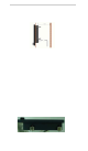
Rear connections
Remarks: The photo above will differ for different model
The rear connect ors are:
1. FUSE
2. Power Input
3. DVI Input
4. VGA Input
5. CVBS-1 Input , CVBS-2 Input and CVBS-3 Input (Composite Video) for AV input
6. RS232 Input
7. USB for Touch control (option)
Planning the i nstallation
Before you install your display, the following points should be considered:
• Power requirements.
• Display location and mounting options.
• Additional accessories, e.g. keyboard or speakers.
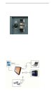
Power requirements
Sunlight Viewable display is designed to run on boat’s power systems, with AC/DC adaptor AcuBrite 15-Nav
are equipped with 9~36V DC wide range power input.
For power connection, please make sure the power cable is tightly connected by two screws of the terminal
block.
The output pin of AC/DC adaptor should be checked and make sure the polarity of voltag e i s conn ect e d
properly.
Grounding the displ ay
It is important that an effective radio frequency (RF) ground is connected to the display. You must ground the
display by connecting the drain wire (shield) of the power input cable to the nearest ground point of the boat’s
RF ground system.
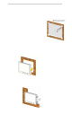
Display location and mounting options
Your display can be mounted using the flush mounting kit supplied. Acubrite12-Nav recommends that you
power the unit and select a suitable mounting location prior to installing the display.
W hen planning the display location, the following points should be considered to ensure safe, comfortable
and reliabl e operation :
•Convenience - the mounting location should be easily accessible to allow operation of the controls and
should enable easy viewing of the display.
Page 7
1
2
3
4
5
7
6