
User Manual


Table Of Contents
- VUE Key Layout
- VUE Soft keys
- Single Axis VUE Tool, and Datum keys
- Readout Parameter Access Code
- Access to Machine Parameter Operations
- Introduction
- Software Version
- VUE
- Symbols within Notes
- VUE Fonts
- Warranty
- Warranty Information:
- I – 1 Fundamentals of Positioning
- Datums
- Actual Position, Nominal Position, and Distance-To-Go
- Absolute Workpiece Positions
- Incremental workpiece positions
- Zero Angle Reference Axis
- Reading head position
- Encoder Reference Marks
- I – 2 General Operations for VUE
- Screen Layout
- VUE Hard Keys
- Power Up
- Reference Mark Evaluation
- Working without reference mark evaluation
- ENABLE/DISABLE REF function
- Operating Modes
- Setup
- Job Setup Parameters
- Units
- Scale Factor
- Mirror
- Diameter Axes
- Near Zero Warning
- Status Bar Settings
- Job Clock
- Console Adjustment
- Language
- Import/Export
- Set/Zero Soft Key
- I – 3 Milling Specific Operations
- Key Functions Detailed
- Tool Hard Key
- Tool Table
- Import/Export
- Tool Radius Compensation feature
- Sign for the length difference DL
- Calling the Tool from the Tool Table
- Datum Setting
- Datum Setting with a Tool
- Presets
- Absolute Distance Preset
- Preparation:
- Incremental Distance Preset
- 1/2 Hard Key
- Circle, and Linear Pattern
- Functions for milling pattern soft keys
- Circle pattern
- Linear Pattern
- Incline & Arc Milling
- Incline Milling
- Arc Milling
- I – 4 Turning Specific Operations
- Key Functions Detailed
- Tool Table
- Tool Display Icon
- Setting Tool Offsets with Tool/Set
- Import/Export
- Setting Tool Offsets with Lock Axis Function
- Calling a Tool from the Tool Table
- Datum Setting
- Setting Datums using LOCK AXIS Function
- Taper Calculator Hard Key
- Presets
- Radius/Diameter Soft Key
- Vectoring
- Coupling
- Z Coupling (turning applications only)
- Enabling Z Coupling
- Disabling Z Coupling
- II – 1 Installation Setup
- Installation Setup Parameters
- Exporting the current Installation Setup:
- Importing a new Tool Table
- Encoder Setup
- Display Configuration
- Error Compensation
- Linear Error Compensation
- Non-Linear Error Compensation
- Starting a Non-linear Error Compensation Table
- Configuring the Compensation Table
- Reading the Graph
- Viewing the Compensation Table
- Exporting the Current Compensation Table
- Importing a New Compensation Table
- Backlash Compensation
- Counter Settings
- Diagnostics
- Keypad Test
- Display Test
- II – 2 Installation and Electrical Connections
- Installation
- Electrical requirements
- Environmental
- Preventative maintenance
- II – 3 Dimensions
- Overview
- Accessory ID Number
46
II – 1 Installation Setup
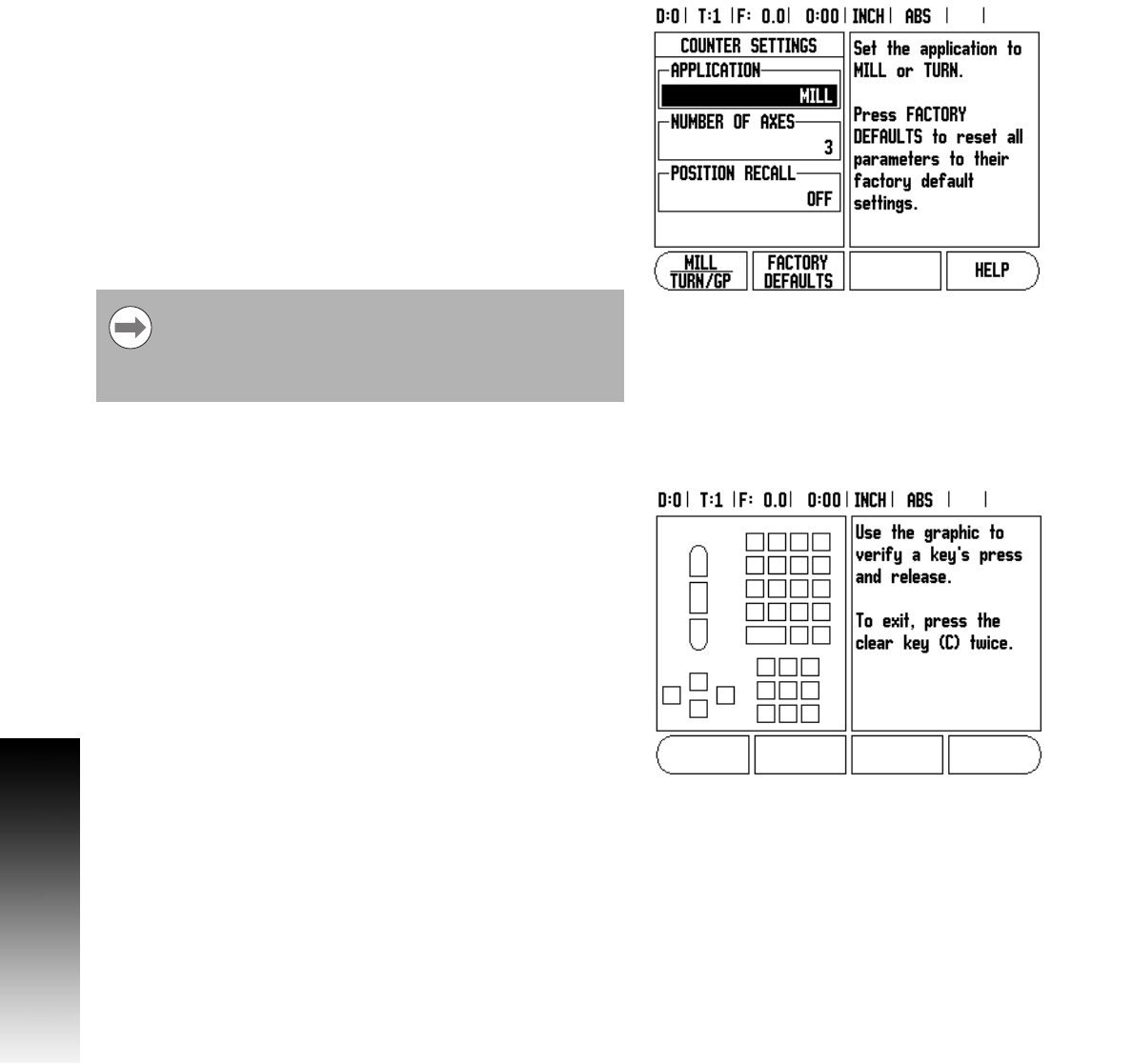
Counter Settings
The Counter Settings feature is the parameter where the operator
defines the user application for the readout. The choices are for milling
or turning applications.
A FACTORY DEFAULT soft key appears in the Counter Settings
choice of options. When pressed, the configuration parameters (based
on either mill or turn) will be reset to factory defaults. The operator will
be prompted to press YES to set parameters to factory default
settings or NO to cancel and return to previous menu screen.
The Number of Axes field sets the number of axes needed. A 1, 2, or
3 soft key will appear to choose between either 1, 2 or 3 axes.
The Position Recall feature, when it is “ON”, will store the last
position of each axis when power was turned off and then redisplay
that position once power is turned back on.
Diagnostics
The Diagnostic menu provides access for testing the keypad and edge
finders.
Keypad Test
An image of the keypad provides an indication when a switch is
pressed and released.
8 Press each hard and soft key to test. A dot will appear on each key
when it has been pressed indicating that it is operating properly.
8 Press the C key two times to exit the keypad test.
Display Test
8 To test the display, press the enter key to set the display to solid
black, solid white, and back to normal.
Note that any movement that occurs while power is off
will be lost. Whenever power has been off it is
recommended to re-establish workpiece datums using the
Reference Mark Evaluation procedure. See "Reference
Mark Evaluation" on page 8.