
User Manual


Table Of Contents
- VUE Key Layout
- VUE Soft keys
- Single Axis VUE Tool, and Datum keys
- Readout Parameter Access Code
- Access to Machine Parameter Operations
- Introduction
- Software Version
- VUE
- Symbols within Notes
- VUE Fonts
- Warranty
- Warranty Information:
- I – 1 Fundamentals of Positioning
- Datums
- Actual Position, Nominal Position, and Distance-To-Go
- Absolute Workpiece Positions
- Incremental workpiece positions
- Zero Angle Reference Axis
- Reading head position
- Encoder Reference Marks
- I – 2 General Operations for VUE
- Screen Layout
- VUE Hard Keys
- Power Up
- Reference Mark Evaluation
- Working without reference mark evaluation
- ENABLE/DISABLE REF function
- Operating Modes
- Setup
- Job Setup Parameters
- Units
- Scale Factor
- Mirror
- Diameter Axes
- Near Zero Warning
- Status Bar Settings
- Job Clock
- Console Adjustment
- Language
- Import/Export
- Set/Zero Soft Key
- I – 3 Milling Specific Operations
- Key Functions Detailed
- Tool Hard Key
- Tool Table
- Import/Export
- Tool Radius Compensation feature
- Sign for the length difference DL
- Calling the Tool from the Tool Table
- Datum Setting
- Datum Setting with a Tool
- Presets
- Absolute Distance Preset
- Preparation:
- Incremental Distance Preset
- 1/2 Hard Key
- Circle, and Linear Pattern
- Functions for milling pattern soft keys
- Circle pattern
- Linear Pattern
- Incline & Arc Milling
- Incline Milling
- Arc Milling
- I – 4 Turning Specific Operations
- Key Functions Detailed
- Tool Table
- Tool Display Icon
- Setting Tool Offsets with Tool/Set
- Import/Export
- Setting Tool Offsets with Lock Axis Function
- Calling a Tool from the Tool Table
- Datum Setting
- Setting Datums using LOCK AXIS Function
- Taper Calculator Hard Key
- Presets
- Radius/Diameter Soft Key
- Vectoring
- Coupling
- Z Coupling (turning applications only)
- Enabling Z Coupling
- Disabling Z Coupling
- II – 1 Installation Setup
- Installation Setup Parameters
- Exporting the current Installation Setup:
- Importing a new Tool Table
- Encoder Setup
- Display Configuration
- Error Compensation
- Linear Error Compensation
- Non-Linear Error Compensation
- Starting a Non-linear Error Compensation Table
- Configuring the Compensation Table
- Reading the Graph
- Viewing the Compensation Table
- Exporting the Current Compensation Table
- Importing a New Compensation Table
- Backlash Compensation
- Counter Settings
- Diagnostics
- Keypad Test
- Display Test
- II – 2 Installation and Electrical Connections
- Installation
- Electrical requirements
- Environmental
- Preventative maintenance
- II – 3 Dimensions
- Overview
- Accessory ID Number
VUE 41
II – 1 Installation Setup
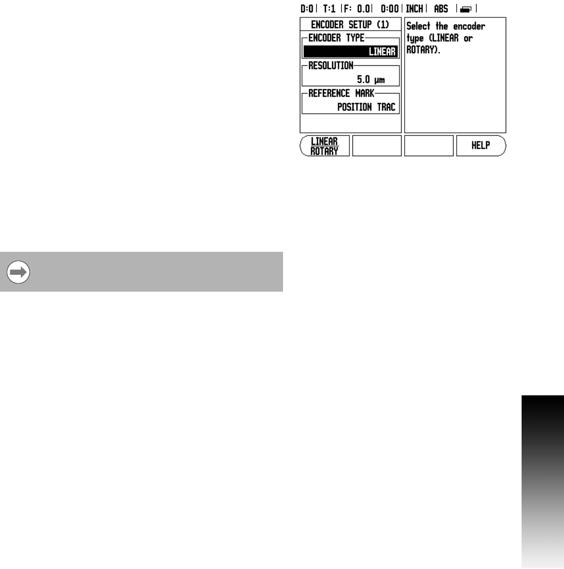
Encoder Setup
The Encoder Setup form is used to set the encoder resolution, and
type (linear, rotary), count direction, reference mark type.
8 Press ENTER. This opens a list of possible encoder inputs.
8 Scroll to the encoder to be changed, and press ENTER.
8 Cursor will be in the Encoder Type field. Select the encoder type by
pressing the LINEAR/ROTARY soft key.
8 For linear encoders, cursor to the Resolution field and use the
COARSER, or FINER soft keys to select the encoder’s resolution (in
µm 10, 5, 2, 1, 0.5). The exact resolution can also be entered using
the numeric key pad. For rotary encoders, enter the number of
counts per revolution.
8 In the Reference Mark field, toggling the REF MARK soft key selects
whether the encoder has no reference signal with NONE, single
reference mark with the SINGLE or with the P-TRAC soft key for
encoders with the Position-Trac™ feature.
8 In the Count Direction field, select the count direction by pressing
the POSITIVE, or NEGATIVE soft key. If the encoder’s count
direction matches the user’s count direction, select positive. If the
directions do not match, select negative.
8 In the Error Monitor field, select whether the system will monitor,
and display encoder errors by selecting ON, or OFF. When an error
message occurs, press the C key to remove it.
The encoder resolution and count direction can also be
established by just moving each axis.