
User Manual


Table Of Contents
- VUE Key Layout
- VUE Soft keys
- Single Axis VUE Tool, and Datum keys
- Readout Parameter Access Code
- Access to Machine Parameter Operations
- Introduction
- Software Version
- VUE
- Symbols within Notes
- VUE Fonts
- Warranty
- Warranty Information:
- I – 1 Fundamentals of Positioning
- Datums
- Actual Position, Nominal Position, and Distance-To-Go
- Absolute Workpiece Positions
- Incremental workpiece positions
- Zero Angle Reference Axis
- Reading head position
- Encoder Reference Marks
- I – 2 General Operations for VUE
- Screen Layout
- VUE Hard Keys
- Power Up
- Reference Mark Evaluation
- Working without reference mark evaluation
- ENABLE/DISABLE REF function
- Operating Modes
- Setup
- Job Setup Parameters
- Units
- Scale Factor
- Mirror
- Diameter Axes
- Near Zero Warning
- Status Bar Settings
- Job Clock
- Console Adjustment
- Language
- Import/Export
- Set/Zero Soft Key
- I – 3 Milling Specific Operations
- Key Functions Detailed
- Tool Hard Key
- Tool Table
- Import/Export
- Tool Radius Compensation feature
- Sign for the length difference DL
- Calling the Tool from the Tool Table
- Datum Setting
- Datum Setting with a Tool
- Presets
- Absolute Distance Preset
- Preparation:
- Incremental Distance Preset
- 1/2 Hard Key
- Circle, and Linear Pattern
- Functions for milling pattern soft keys
- Circle pattern
- Linear Pattern
- Incline & Arc Milling
- Incline Milling
- Arc Milling
- I – 4 Turning Specific Operations
- Key Functions Detailed
- Tool Table
- Tool Display Icon
- Setting Tool Offsets with Tool/Set
- Import/Export
- Setting Tool Offsets with Lock Axis Function
- Calling a Tool from the Tool Table
- Datum Setting
- Setting Datums using LOCK AXIS Function
- Taper Calculator Hard Key
- Presets
- Radius/Diameter Soft Key
- Vectoring
- Coupling
- Z Coupling (turning applications only)
- Enabling Z Coupling
- Disabling Z Coupling
- II – 1 Installation Setup
- Installation Setup Parameters
- Exporting the current Installation Setup:
- Importing a new Tool Table
- Encoder Setup
- Display Configuration
- Error Compensation
- Linear Error Compensation
- Non-Linear Error Compensation
- Starting a Non-linear Error Compensation Table
- Configuring the Compensation Table
- Reading the Graph
- Viewing the Compensation Table
- Exporting the Current Compensation Table
- Importing a New Compensation Table
- Backlash Compensation
- Counter Settings
- Diagnostics
- Keypad Test
- Display Test
- II – 2 Installation and Electrical Connections
- Installation
- Electrical requirements
- Environmental
- Preventative maintenance
- II – 3 Dimensions
- Overview
- Accessory ID Number
34 I
I – 4 Turning Specific Operations
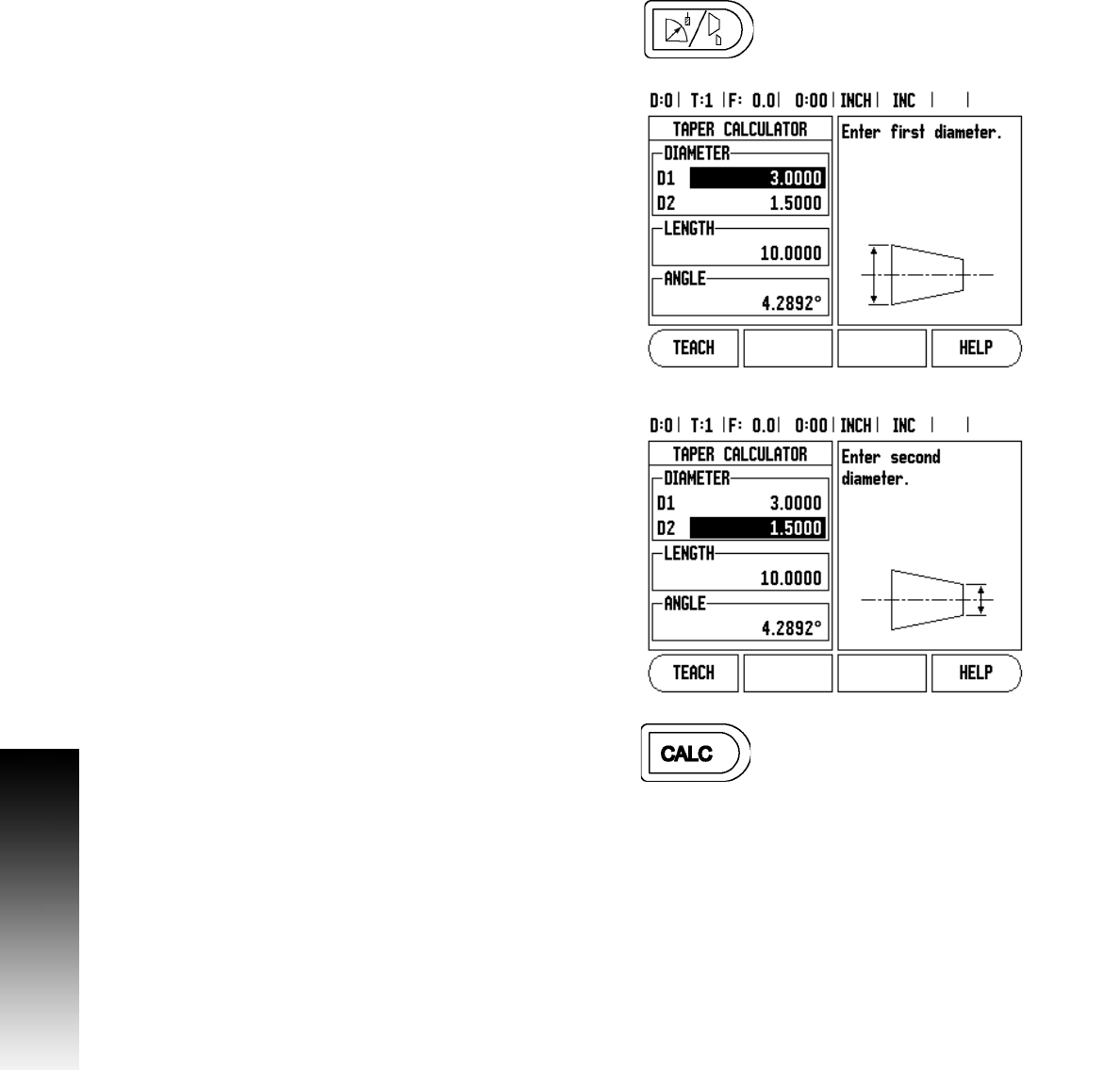
Taper Calculator Hard Key
Use the taper calculator to caculate taper angle.
Calculate tapers either by entering dimensions from a print, or by
touching a tapered workpiece with a tool, or indicator.
Entry values:
For the taper ratio, calculation requires:
Length of the taper
Change in the radius of the taper.
For taper calculation using both diameters (D1, D2), and length
requires:
Starting diameter
End diameter
Length of the taper
Using Taper Calculator
8 Press the CALC hard key: The soft key selection now changes to
include the taper calculator funtions.
8 To calculate the taper angle using two diameters, and length
between, press the taper: di/D2/l soft keys.
8 First taper point, diameter 1, either enter a point using the numeic
keys, and press enter, or touch the tool to one point, and press
note.
8 Repeat this for the diameter 2 field. When using the NOTE key, the
taper angle is automatically calculated. When entering data
numerically, enter data into the length field, and press ENTER: The
taper angle will appear in the angle field.
8 To calculate angles using the ratio of the diameter, change to length,
and press the taper: RATIO soft key.
8 Using the numeric keys, enter data into the ENTRY 1, and ENTRY 2
fields.
8 Press ENTER after each selection: The calculated ratio, and the
angle will appear in their respective fields.