
User Manual


Table Of Contents
- VUE Key Layout
- VUE Soft keys
- Single Axis VUE Tool, and Datum keys
- Readout Parameter Access Code
- Access to Machine Parameter Operations
- Introduction
- Software Version
- VUE
- Symbols within Notes
- VUE Fonts
- Warranty
- Warranty Information:
- I – 1 Fundamentals of Positioning
- Datums
- Actual Position, Nominal Position, and Distance-To-Go
- Absolute Workpiece Positions
- Incremental workpiece positions
- Zero Angle Reference Axis
- Reading head position
- Encoder Reference Marks
- I – 2 General Operations for VUE
- Screen Layout
- VUE Hard Keys
- Power Up
- Reference Mark Evaluation
- Working without reference mark evaluation
- ENABLE/DISABLE REF function
- Operating Modes
- Setup
- Job Setup Parameters
- Units
- Scale Factor
- Mirror
- Diameter Axes
- Near Zero Warning
- Status Bar Settings
- Job Clock
- Console Adjustment
- Language
- Import/Export
- Set/Zero Soft Key
- I – 3 Milling Specific Operations
- Key Functions Detailed
- Tool Hard Key
- Tool Table
- Import/Export
- Tool Radius Compensation feature
- Sign for the length difference DL
- Calling the Tool from the Tool Table
- Datum Setting
- Datum Setting with a Tool
- Presets
- Absolute Distance Preset
- Preparation:
- Incremental Distance Preset
- 1/2 Hard Key
- Circle, and Linear Pattern
- Functions for milling pattern soft keys
- Circle pattern
- Linear Pattern
- Incline & Arc Milling
- Incline Milling
- Arc Milling
- I – 4 Turning Specific Operations
- Key Functions Detailed
- Tool Table
- Tool Display Icon
- Setting Tool Offsets with Tool/Set
- Import/Export
- Setting Tool Offsets with Lock Axis Function
- Calling a Tool from the Tool Table
- Datum Setting
- Setting Datums using LOCK AXIS Function
- Taper Calculator Hard Key
- Presets
- Radius/Diameter Soft Key
- Vectoring
- Coupling
- Z Coupling (turning applications only)
- Enabling Z Coupling
- Disabling Z Coupling
- II – 1 Installation Setup
- Installation Setup Parameters
- Exporting the current Installation Setup:
- Importing a new Tool Table
- Encoder Setup
- Display Configuration
- Error Compensation
- Linear Error Compensation
- Non-Linear Error Compensation
- Starting a Non-linear Error Compensation Table
- Configuring the Compensation Table
- Reading the Graph
- Viewing the Compensation Table
- Exporting the Current Compensation Table
- Importing a New Compensation Table
- Backlash Compensation
- Counter Settings
- Diagnostics
- Keypad Test
- Display Test
- II – 2 Installation and Electrical Connections
- Installation
- Electrical requirements
- Environmental
- Preventative maintenance
- II – 3 Dimensions
- Overview
- Accessory ID Number
30 I
I – 4 Turning Specific Operations
I – 4 Turning Specific Operations
Key Functions Detailed
This section discusses operations specific to turning applications only.
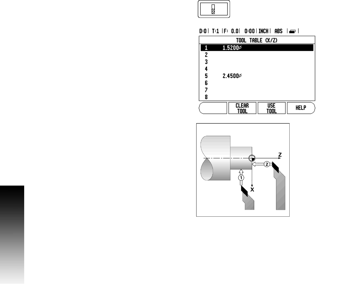
Tool Table
The VUE can store the dimensional offsets for up to 16 tools. When
changing a workpiece, and establish a new datum, all tools are
automatically referenced from the new datum.
Before a tool can be used, enter its offset (the cutting edge position).
Tool offsets can be set using the Tool/Set, or Lock Axis features. See
the following examples for instructions on Tool Offsetting.
Tool Display Icon
The ∅ icon is used to indicate that the displayed value is a diameter
value. No icon visible indicates that the display is a radius value.
Setting Tool Offsets with Tool/Set
Example 1: Using Tool/Set
The Tool/Set operation can be used to set a tool’s offset using a tool
when the diameter of the workpiece is known.
8 Touch the known diameter in the X axis (1).
8 Press the TOOL hard key.
8 Scroll to the desired tool.
8 Press the ENTER key.
8 Select the X axis key.
8 Enter the position of the tool tip, for example, X= .100. Remember
to ensure the VUE is in diameter display mode (Ø) if a diameter value
is used.
8 Touch the workpiece face with the tool.
8 Cursor to the Z axis (2), then set the position display for the tool tip
to zero, Z=0.
8 Press ENTER.