
User Manual


Table Of Contents
- VUE Key Layout
- VUE Soft keys
- Single Axis VUE Tool, and Datum keys
- Readout Parameter Access Code
- Access to Machine Parameter Operations
- Introduction
- Software Version
- VUE
- Symbols within Notes
- VUE Fonts
- Warranty
- Warranty Information:
- I – 1 Fundamentals of Positioning
- Datums
- Actual Position, Nominal Position, and Distance-To-Go
- Absolute Workpiece Positions
- Incremental workpiece positions
- Zero Angle Reference Axis
- Reading head position
- Encoder Reference Marks
- I – 2 General Operations for VUE
- Screen Layout
- VUE Hard Keys
- Power Up
- Reference Mark Evaluation
- Working without reference mark evaluation
- ENABLE/DISABLE REF function
- Operating Modes
- Setup
- Job Setup Parameters
- Units
- Scale Factor
- Mirror
- Diameter Axes
- Near Zero Warning
- Status Bar Settings
- Job Clock
- Console Adjustment
- Language
- Import/Export
- Set/Zero Soft Key
- I – 3 Milling Specific Operations
- Key Functions Detailed
- Tool Hard Key
- Tool Table
- Import/Export
- Tool Radius Compensation feature
- Sign for the length difference DL
- Calling the Tool from the Tool Table
- Datum Setting
- Datum Setting with a Tool
- Presets
- Absolute Distance Preset
- Preparation:
- Incremental Distance Preset
- 1/2 Hard Key
- Circle, and Linear Pattern
- Functions for milling pattern soft keys
- Circle pattern
- Linear Pattern
- Incline & Arc Milling
- Incline Milling
- Arc Milling
- I – 4 Turning Specific Operations
- Key Functions Detailed
- Tool Table
- Tool Display Icon
- Setting Tool Offsets with Tool/Set
- Import/Export
- Setting Tool Offsets with Lock Axis Function
- Calling a Tool from the Tool Table
- Datum Setting
- Setting Datums using LOCK AXIS Function
- Taper Calculator Hard Key
- Presets
- Radius/Diameter Soft Key
- Vectoring
- Coupling
- Z Coupling (turning applications only)
- Enabling Z Coupling
- Disabling Z Coupling
- II – 1 Installation Setup
- Installation Setup Parameters
- Exporting the current Installation Setup:
- Importing a new Tool Table
- Encoder Setup
- Display Configuration
- Error Compensation
- Linear Error Compensation
- Non-Linear Error Compensation
- Starting a Non-linear Error Compensation Table
- Configuring the Compensation Table
- Reading the Graph
- Viewing the Compensation Table
- Exporting the Current Compensation Table
- Importing a New Compensation Table
- Backlash Compensation
- Counter Settings
- Diagnostics
- Keypad Test
- Display Test
- II – 2 Installation and Electrical Connections
- Installation
- Electrical requirements
- Environmental
- Preventative maintenance
- II – 3 Dimensions
- Overview
- Accessory ID Number
26 I
I – 3 Milling Specific Operations
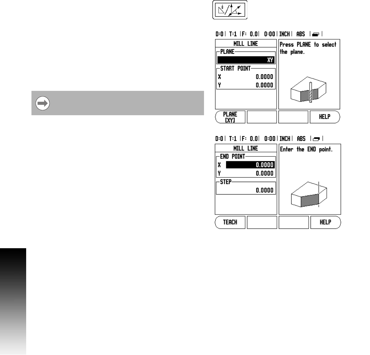
Incline Milling
Entry Form:
8 The Incline Milling form is used to specify the flat surface to be
milled. Press the INCLINE MILLING hard key to open the form
8 Plane - Select the plane by pressing the PLANE soft key. The current
selection is shown on the soft key, and in the plane field. The
graphic in the message box aids in selecting the correct plane.
8 Start Point: Enter the coordinates of the start point, or press teach
to set the coordinate to the current position.
8 End Point: Enter the coordinates of the end point, or press teach to
set the coordinate to current position.
8 Step: Enter the step size. When milling, this is the distance between
each pass, or each step along the line.
8 Press ENTER, to execute the surface milling operation.
8 Press C to exit the form without executing. Settings are retained
until power is turned off.
Executing the Incline Milling feature
8 Execute the milling operation by opening the entry form, and
pressing the enter key. The screen switches to the incremental
DRO view.
8 Initially, the DRO shows the current incremental moving distance
from the start point. Move to the start point and make a plunge cut,
or the first pass across the surface.
8 Press the NEXT PASS soft key to continue with the next step along
the contour. After pressing next pass, the incremental display
shows the distance from the next step along the line’s contour.
8 If no step size was specified, the incremental display always shows
the distance from the closest point on the line. To follow the
contour, move the two axes in small steps, keeping the (X, Y)
positions as close to 0 as possible.
The Step size is optional. If the value is zero, the operator
decides at run-time how far to move between each step.