
User Manual


Table Of Contents
- VUE Key Layout
- VUE Soft keys
- Single Axis VUE Tool, and Datum keys
- Readout Parameter Access Code
- Access to Machine Parameter Operations
- Introduction
- Software Version
- VUE
- Symbols within Notes
- VUE Fonts
- Warranty
- Warranty Information:
- I – 1 Fundamentals of Positioning
- Datums
- Actual Position, Nominal Position, and Distance-To-Go
- Absolute Workpiece Positions
- Incremental workpiece positions
- Zero Angle Reference Axis
- Reading head position
- Encoder Reference Marks
- I – 2 General Operations for VUE
- Screen Layout
- VUE Hard Keys
- Power Up
- Reference Mark Evaluation
- Working without reference mark evaluation
- ENABLE/DISABLE REF function
- Operating Modes
- Setup
- Job Setup Parameters
- Units
- Scale Factor
- Mirror
- Diameter Axes
- Near Zero Warning
- Status Bar Settings
- Job Clock
- Console Adjustment
- Language
- Import/Export
- Set/Zero Soft Key
- I – 3 Milling Specific Operations
- Key Functions Detailed
- Tool Hard Key
- Tool Table
- Import/Export
- Tool Radius Compensation feature
- Sign for the length difference DL
- Calling the Tool from the Tool Table
- Datum Setting
- Datum Setting with a Tool
- Presets
- Absolute Distance Preset
- Preparation:
- Incremental Distance Preset
- 1/2 Hard Key
- Circle, and Linear Pattern
- Functions for milling pattern soft keys
- Circle pattern
- Linear Pattern
- Incline & Arc Milling
- Incline Milling
- Arc Milling
- I – 4 Turning Specific Operations
- Key Functions Detailed
- Tool Table
- Tool Display Icon
- Setting Tool Offsets with Tool/Set
- Import/Export
- Setting Tool Offsets with Lock Axis Function
- Calling a Tool from the Tool Table
- Datum Setting
- Setting Datums using LOCK AXIS Function
- Taper Calculator Hard Key
- Presets
- Radius/Diameter Soft Key
- Vectoring
- Coupling
- Z Coupling (turning applications only)
- Enabling Z Coupling
- Disabling Z Coupling
- II – 1 Installation Setup
- Installation Setup Parameters
- Exporting the current Installation Setup:
- Importing a new Tool Table
- Encoder Setup
- Display Configuration
- Error Compensation
- Linear Error Compensation
- Non-Linear Error Compensation
- Starting a Non-linear Error Compensation Table
- Configuring the Compensation Table
- Reading the Graph
- Viewing the Compensation Table
- Exporting the Current Compensation Table
- Importing a New Compensation Table
- Backlash Compensation
- Counter Settings
- Diagnostics
- Keypad Test
- Display Test
- II – 2 Installation and Electrical Connections
- Installation
- Electrical requirements
- Environmental
- Preventative maintenance
- II – 3 Dimensions
- Overview
- Accessory ID Number
VUE 23
I – 3 Milling Specific Operations
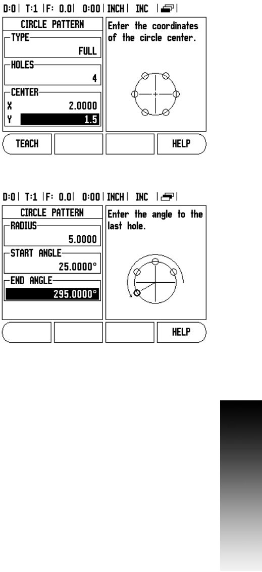
Circle pattern
Example: Enter data, and execute a circle pattern.
Holes (no. of): 4
Coordinates of center: X = 2.0” / Y = 1.5”
Bolt circle radius: 5
Start angle: Angle between X axis, and first hole: 25°
Hole depth: Z = -0.25”
1st step: Enter data
8 Press CIRCLE PATTERN hard key.
8 Enter the type of circle pattern (full). Cursor to the next field.
8 Enter the number of holes (4).
8 Enter the X, and Y coordinates of the circle center (X=2.0), (Y=1.5).
Cursor to the next field.
8 Enter the radius of the circle pattern (5).
8 Enter the start angle (25°).
8 Enter the end angle (295°) (this can only be changed if entering a
“segment”). The End Angle is defined as the angle from the positive
X-axis to the end of the pattern.
8 Enter the depth when needed. The depth of the hole is optional, and
may be left blank. If not required, press ENTER.
8 Three views are available: Incremental DRO, Pattern Graphic, and
Absolute DRO. Press the VIEW soft key to toggle through the
available screens.
2nd step: Drill
8 Move to hole:
8 Traverse the X, and Y axes until display value zero.
8 Drill:
8 Traverse to display value zero in the tool axis. After drilling, retract
the drill in tool axis.
8 Press the NEXT HOLE soft key.
8 Continue to drill the remaining holes in the same way.
8 When the pattern is complete, press the END soft key.