
User Manual


Table Of Contents
- VUE Key Layout
- VUE Soft keys
- Single Axis VUE Tool, and Datum keys
- Readout Parameter Access Code
- Access to Machine Parameter Operations
- Introduction
- Software Version
- VUE
- Symbols within Notes
- VUE Fonts
- Warranty
- Warranty Information:
- I – 1 Fundamentals of Positioning
- Datums
- Actual Position, Nominal Position, and Distance-To-Go
- Absolute Workpiece Positions
- Incremental workpiece positions
- Zero Angle Reference Axis
- Reading head position
- Encoder Reference Marks
- I – 2 General Operations for VUE
- Screen Layout
- VUE Hard Keys
- Power Up
- Reference Mark Evaluation
- Working without reference mark evaluation
- ENABLE/DISABLE REF function
- Operating Modes
- Setup
- Job Setup Parameters
- Units
- Scale Factor
- Mirror
- Diameter Axes
- Near Zero Warning
- Status Bar Settings
- Job Clock
- Console Adjustment
- Language
- Import/Export
- Set/Zero Soft Key
- I – 3 Milling Specific Operations
- Key Functions Detailed
- Tool Hard Key
- Tool Table
- Import/Export
- Tool Radius Compensation feature
- Sign for the length difference DL
- Calling the Tool from the Tool Table
- Datum Setting
- Datum Setting with a Tool
- Presets
- Absolute Distance Preset
- Preparation:
- Incremental Distance Preset
- 1/2 Hard Key
- Circle, and Linear Pattern
- Functions for milling pattern soft keys
- Circle pattern
- Linear Pattern
- Incline & Arc Milling
- Incline Milling
- Arc Milling
- I – 4 Turning Specific Operations
- Key Functions Detailed
- Tool Table
- Tool Display Icon
- Setting Tool Offsets with Tool/Set
- Import/Export
- Setting Tool Offsets with Lock Axis Function
- Calling a Tool from the Tool Table
- Datum Setting
- Setting Datums using LOCK AXIS Function
- Taper Calculator Hard Key
- Presets
- Radius/Diameter Soft Key
- Vectoring
- Coupling
- Z Coupling (turning applications only)
- Enabling Z Coupling
- Disabling Z Coupling
- II – 1 Installation Setup
- Installation Setup Parameters
- Exporting the current Installation Setup:
- Importing a new Tool Table
- Encoder Setup
- Display Configuration
- Error Compensation
- Linear Error Compensation
- Non-Linear Error Compensation
- Starting a Non-linear Error Compensation Table
- Configuring the Compensation Table
- Reading the Graph
- Viewing the Compensation Table
- Exporting the Current Compensation Table
- Importing a New Compensation Table
- Backlash Compensation
- Counter Settings
- Diagnostics
- Keypad Test
- Display Test
- II – 2 Installation and Electrical Connections
- Installation
- Electrical requirements
- Environmental
- Preventative maintenance
- II – 3 Dimensions
- Overview
- Accessory ID Number
22 I
I – 3 Milling Specific Operations
8 To preset the Z axis:
8 Press the Z axis key.
8 Press the ENTER key (use last entered preset).
8 Drill hole 2: Traverse Z axis until the display value is zero. The square
in the near zero warning is now centered between the two triangular
marks.
8 Retract the drill.
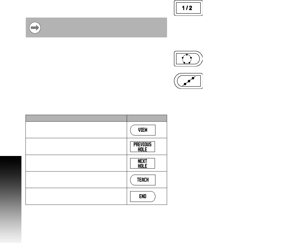
1/2 Hard Key
The 1/2 hard key is used to find the centerline (or midpoint) between
two locations along a selected axis of a workpiece. This can be
performed in either Actual Value, or Distance-To-Go mode.
Circle, and Linear Pattern
This section describes the hole pattern functions for Circle, and Linear
patterns.
Press the CIRCLE PATTERN, or LINEAR PATTERN hard key to access
the Pattern function then enter the required data. VUE then calculates
the positions of all the holes, and displays the pattern graphically on
the screen.
The View Graphic enables verification of the hole pattern before any
machining starts. It is also useful when: selecting holes directly,
executing holes separately, and skipping holes.
Functions for milling pattern soft keys
This feature will change datum locations when in Actual
Value mode.
Function Soft key
Press the VIEW soft key to see the layout of
the current pattern.
Press to go to previous hole.
Press to manually advance to the next hole.
Press to use the current absolute position.
Press to end drilling.