
User Manual


Table Of Contents
- VUE Key Layout
- VUE Soft keys
- Single Axis VUE Tool, and Datum keys
- Readout Parameter Access Code
- Access to Machine Parameter Operations
- Introduction
- Software Version
- VUE
- Symbols within Notes
- VUE Fonts
- Warranty
- Warranty Information:
- I – 1 Fundamentals of Positioning
- Datums
- Actual Position, Nominal Position, and Distance-To-Go
- Absolute Workpiece Positions
- Incremental workpiece positions
- Zero Angle Reference Axis
- Reading head position
- Encoder Reference Marks
- I – 2 General Operations for VUE
- Screen Layout
- VUE Hard Keys
- Power Up
- Reference Mark Evaluation
- Working without reference mark evaluation
- ENABLE/DISABLE REF function
- Operating Modes
- Setup
- Job Setup Parameters
- Units
- Scale Factor
- Mirror
- Diameter Axes
- Near Zero Warning
- Status Bar Settings
- Job Clock
- Console Adjustment
- Language
- Import/Export
- Set/Zero Soft Key
- I – 3 Milling Specific Operations
- Key Functions Detailed
- Tool Hard Key
- Tool Table
- Import/Export
- Tool Radius Compensation feature
- Sign for the length difference DL
- Calling the Tool from the Tool Table
- Datum Setting
- Datum Setting with a Tool
- Presets
- Absolute Distance Preset
- Preparation:
- Incremental Distance Preset
- 1/2 Hard Key
- Circle, and Linear Pattern
- Functions for milling pattern soft keys
- Circle pattern
- Linear Pattern
- Incline & Arc Milling
- Incline Milling
- Arc Milling
- I – 4 Turning Specific Operations
- Key Functions Detailed
- Tool Table
- Tool Display Icon
- Setting Tool Offsets with Tool/Set
- Import/Export
- Setting Tool Offsets with Lock Axis Function
- Calling a Tool from the Tool Table
- Datum Setting
- Setting Datums using LOCK AXIS Function
- Taper Calculator Hard Key
- Presets
- Radius/Diameter Soft Key
- Vectoring
- Coupling
- Z Coupling (turning applications only)
- Enabling Z Coupling
- Disabling Z Coupling
- II – 1 Installation Setup
- Installation Setup Parameters
- Exporting the current Installation Setup:
- Importing a new Tool Table
- Encoder Setup
- Display Configuration
- Error Compensation
- Linear Error Compensation
- Non-Linear Error Compensation
- Starting a Non-linear Error Compensation Table
- Configuring the Compensation Table
- Reading the Graph
- Viewing the Compensation Table
- Exporting the Current Compensation Table
- Importing a New Compensation Table
- Backlash Compensation
- Counter Settings
- Diagnostics
- Keypad Test
- Display Test
- II – 2 Installation and Electrical Connections
- Installation
- Electrical requirements
- Environmental
- Preventative maintenance
- II – 3 Dimensions
- Overview
- Accessory ID Number
16 I
I – 3 Milling Specific Operations
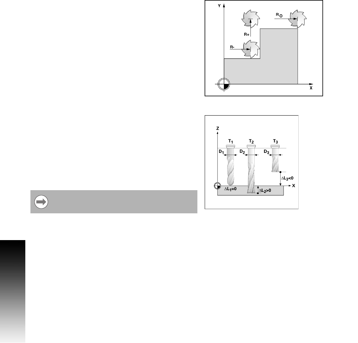
Tool Radius Compensation feature
This allows workpiece dimensions to be entered directly from the
drawing. The displayed distance to go is then automatically
lengthened (R+), or shortened (R–) by the value of the tool radius. for
more information see "Presets" on page 19.
The length offset may be entered as a known value, or the VUE may
determine the offset automatically. The tool length is the difference in
length
ΔL between the tool, and the reference tool. The length
difference is indicated with the “
Δ“ symbol. The reference tool is
indicated by T1.
Sign for the length difference
ΔL
If the tool is longer than the reference tool:
ΔL > 0 (+).
If the tool is shorter than the reference tool:
ΔL < 0 (–).
As indicated above it is also possible to have the VUE determine a
tool’s length offset. This method involves touching the tip of each tool
to a common reference surface. This allows the VUE to determine the
difference between the length of each tool.
Move the tool until its tip is touching the reference surface. Press the
TEACH LENGTH soft key. The VUE will calculate an offset relative to
this surface. Repeat the procedure for each additional tool using the
same reference surface.
Only the tools set using the same reference surface may
be changed without having to reset the datum.